
ESE101: Microcontroller Peripherals, GPIOs, and Blinking Lights: Part 1
Let’s get back to the microcontroller’s blinky demo code and dig into how it made the light blink.
You already know that a microcontroller is just instructions, registers, and memory. We’ve seen how instructions can change registers and memory, and cause different instructions to run depending on what’s in registers and memory. Until now, we’ve only considered things inside the microcontroller.
So how does a microcontroller interact with stuff outside the microcontroller, like the blinky light?
It uses a peripheral. A peripheral is a part of a microcontroller that interfaces with the outside world. Examples of peripherals are GPIOs, I2C, SPI, UART, timers, and USB. (We’ll define these later.)
Note: This post will reference a bunch of different links and documents to fully explain what peripherals are and how to use them.I’ve pulled the relevant parts into this post so you don’t have to click away to see them, but the links are there so you can explore more on your own after you read the post.
GPIOs
GPIO stands for General Purpose Input/Output pin. (We say “GPIO”, “GPIO pin”, or even just “IO”, they mean the same thing.) Each of a microcontroller chip’s little metal pins has a purpose. It might be a single dedicated purpose like connecting the chip to power or ground, or it might be a GPIO pin that you, the programmer, can configure in different ways.
GPIOs can be configured as either inputs or outputs. As an input, a GPIO pin tells the microcontroller what voltage is present on the pin. For example, an input GPIO configuration could be used to tell the microcontroller if a button is being pressed.
As an output, the microcontroller chooses to set the GPIO pin to output either a high or low voltage. An output GPIO configuration can be used to turn an LED on or off, as in our blinky example. A GPIO can also be configured as a tri-state output, but we’ll ignore that for now.
So how do we control GPIOs? I’m glad you asked!
Controlling GPIOs
A microcontroller usually sets aside a chunk of memory for controlling peripherals. This chunk of memory is called the peripheral memory space or peripheral address space.
At the end of the last post I showed you that the bottom part of the MSP430’s memory map was reserved for peripherals: this is the MSP430’s peripheral address space. Here’s the simplified memory map from last time:

The last rows of the MSP430’s memory map tells us that addresses 0x000000 - 0x000FFF are used for the peripherals. This means that each memory location from 0 - 0xFFF corresponds to a peripheral. The datasheet breaks down the MSP430’s peripheral address space further like this:

Each row is a different peripheral, and each peripheral has:
- a base address: the first (smallest) address a peripheral uses
- a range: the range of addresses a peripheral uses, which is added to the base address to get a complete address.
For example:
- The first set of GPIO pins are called “Port P1 and P2”. You can see from that table that their base address is 0x0200 (remember that’s the same thing as 0200h), and their address range is 0x000-0x01F, meaning they use addresses 0x0200-0x021F.
- The second set of GPIO pins are called “Port P3 and P4”. Their base address is 0x0220 and address range is 0x000-0x00B. This means they use addresses 0x0220-0x022B.
What about the GPIO that controls the blinky light on the MSP430 LaunchPad dev board? What peripheral is that, where does it live in memory, and how do we actually do something with the LED?
What Peripheral Is the LED Connected To?
Let’s look at the LaunchPad board to find out what peripheral the LED is connected to:
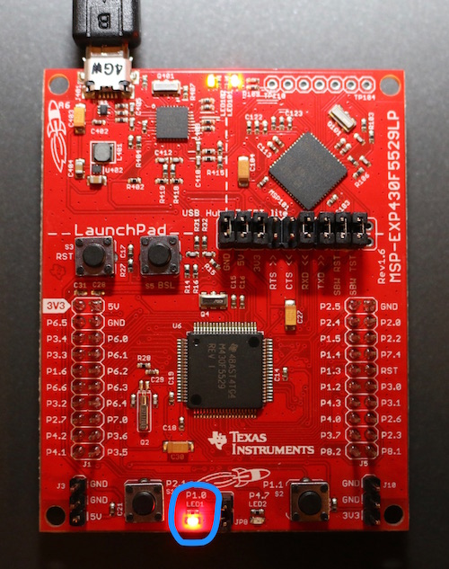
I’ve circled the blinking LED on the bottom of the board in blue. You can see the white writing just above LED1 says “P1.0”. This means that the LED is connected to GPIO pin P1.0 on the MSP430. When that GPIO changes state, so will the LED.
Our MSP430’s GPIOs are grouped into ports called P1-P8, and most ports control 8 individual GPIO pins. “P1.0” means the LED is connected GPIO port P1, bit 0.
(Fun fact: the writing on a PCB is called the silk screen.)
Where Does GPIO Port P1 Live in Memory?
Looking back at the table from the datasheet we see that GPIO ports P1 and P2 are combined into a single entry that has base address 0x0200 and goes up to address 0x021F (that’s 0x200 + 0x01F):

How Do I Do Something With The LED on P1?
We know our LED is connected to P1.0, and now we know that P1 has a base address of 0x0200. But what does that mean? How do we actually *DO* something with the LED, like turn it on?
All peripherals are controlled by bits that are grouped into peripheral control registers. Peripheral control registers aren’t directly accessible to instructions like the R0-R15 registers are. Instead, instructions access the peripheral control registers by using addresses in the peripheral memory space.
Here’s a high level picture of the microcontroller and the GPIO peripheral:

In this image, we see the the physical microcontroller chip boundary as the outer double line. The registers R0-R15 and memory are here, just as in previous examples. The GPIO port 1 and 2 peripheral control registers are on the right. Instructions will read and write these control registers using the peripheral’s address space, which is 0x0200-0x021F. Each peripheral memory address is connected to its control register, shown as a dashed red arrow/line in the drawing.
If an instruction writes a value to address 0x0200, the microcontroller knows that address corresponds to the GPIO Port 1 and 2 peripheral, and it writes the value into the first control register for that peripheral. Likewise if an instruction reads from address 0x0205 the microcontroller reads the value stored in the corresponding peripheral control register and gives the instruction that value.
It’s important to realize that there is no actual RAM or flash memory at address 0x0200-0x021F: the microcontroller has mapped the peripheral control registers at the addresses 0x0200-0x021F. It’s sort of like the microcontroller pretends 0x0200 is a real memory location, but whenever an instruction uses memory address 0x0200 the microcontroller realizes, “Hey! That’s not real memory, the instruction actually wants to talk to the peripheral control register over here!”
The idea of assigning memory addresses to peripherals is called memory mapping or memory mapped I/O or memory mapped peripherals.
The dotted-line box labeled “GPIO circuitry” is there to tell you that there’s a bunch of circuits that use the values in the GPIO configuration registers to control the pins.
Next week we’ll learn what specific registers are used to control GPIOs.
This post is part of a series. Check out the complete Embedded Software Engineering 101 series here.