
ESE101: Memory: It’s All About Location, Location, Location
ESE101 started with a fictional microcontroller that had a very small memory: 8 memory locations at first, and later 16 memory locations. Small memories are useful for simple examples, but real microcontrollers have far larger memories. This week we’ll take a closer look at exactly what real microcontroller memories look like.
Types of Memories
Before we dive in, I need to explain the different types of memories. The two main types of memories used in microcontrollers are RAM and flash.
RAM stands for Random Access Memory. RAM loses its contents when it loses power, so it’s only useful when a chip is powered on. You can change any part of RAM at any time - it’s the most flexible of all memory types. RAM is used for storing variables and doing computation.
Flash memory retains its contents when it loses power. This means that whatever is put in flash memory stays there after a chip is powered off, and is still there the next time the chip is powered on. This makes flash memory a great place to put the instructions that make up your program. The downside is flash can’t be changed easily: if you want to change a value in flash you first have to erase a chunk of flash (usually at least 4KB), which is slow, and then rewrite everything in the chunk of flash you just erased including your new value. This means that flash memory is a terrible place to put stuff that needs to change often, but a great place to put stuff that rarely or never changes (like your program).
Note: Andrei Chichak has a great explanation of RAM, flash, and other common memory types as part of his Embedded Wednesdays series - check it out for more detailed info.
A Memory Map
Let’s take a look at TI’s memory map for the MSP430F5529, the microcontroller we’re using for ESE101. Warning: this table is huge, ugly, and hard to read - I’m just showing you what it looks like, don’t be overwhelmed by trying to understand it. I’ll zoom in on the parts we care about shortly.

A memory map is exactly what it sounds like: a map showing how memory is organized. It’s also called the address map, memory organization, or memory layout. You can find the memory map in a microcontroller’s datasheet or reference manual.
You’ll notice that there are four main columns in that table: each is for a different subset of MSP430 variants. The MSP430F5529 is on the far right hand column, so let’s zoom into it (I cut out the other three columns):

There’s a lot of information here, so let’s break it down starting from the top.
The first line tells us that our MSP430F5529 has 128KB of flash memory. Remember, flash is usually where our program’s instructions are stored. 128KB is big enough for a reasonably large program: it’s about big enough for a Fitbit or a consumer toy, more than enough room for a tiny quadcopter, but not big enough for BB-8.
The second line says something called the interrupt vector lives at addresses 00FFFFh - 00FF80h. We’re going to ignore what an interrupt vector is until a later post, so don’t worry about that. However, the 00FFFFh - 00FF80h notation can be confusing for a few reasons so let me explain what it means.
Confusing Reason 1: Hex
Numbers that end in “h” mean that they’re in base-16, also called hexadecimal or hex numbers. Hex numbers are more commonly written with a leading “0x” instead of a trailing “h”, like 0x00FFFF or 0x00FF80. Memory addresses are almost always written as hex instead of decimal. This may seem bizarre, but it turns out that hex numbers are more convenient to work with because a hex number is shorter to write than its decimal equivalent, and because we end up manipulating addresses using powers of two (adding/subtracting/dividing/multiplying by 2, 4, 8, 16, 32, 64, etc). And since our microprocessor uses binary, it tends to prefer things that are powers of two.
If you look at our addresses above, say 00FFFFh - 00FF80h, in decimal those are 65535-65408. Those decimal numbers don’t tell you much. But once you get used to hex, you’ll see that FFFFh minus FF80h is 7Fh bytes which is 127 bytes, one short of 80h (128 == power of two!).
(Of course if I had spent my entire career only using decimal numbers and never using hex numbers, maybe I’d say that 65535-65408 made more sense than 00FFFFh - 00FF80h, but I doubt it.)
After you work with embedded systems for a while you’ll learn to like hex, I promise.
Confusing Reason 2: Leading 0’s
The number 00FFFFh is exactly the same number as 0FFFFh and also FFFFh. Putting 0’s in the front of a number doesn’t change its value, so why did the author of the datasheet put the leading 0’s there?
Leading 0’s are used to show the full width of a number. The MSP430 uses 20-bit addresses, which means the largest address is the largest 20-bit number, which is FFFFFh, which has five hex digits. When writing out a bunch of numbers with the same width, it can be clearer to write them as:
00001h
00010h
10000h
Instead of:
1h
10h
10000h
Writing all numbers with the same number of digits helps them line up on the page, making visual comparisons easier.
"But hang on, Chris!", you’re saying - if the leading 0’s are used to show the full width of the MSP430’s 20-bit addresses, which should be five hex digits, why does the MSP430 memory map table show *six* hex digits instead of five? It’s just a guess, but I bet the addresses in the table are copied from some code, and if an address like 0FFFFFh was written as five hex digits, without the leading 0, it would be FFFFFh, which is interpreted as a variable name instead of a number in some programming languages. The leading 0 tells the compiler that this is a number, not a variable name.
To make it even more confusing, elsewhere in the datasheet they use five hex digits for addresses, so I’m not sure why this memory map table is different. I guess the conclusion is: writing and explaining things is hard.
If you’re new to hex numbers please check out tutorials on the web, here’s a few:
Also, I recommend the free, cross-platform calculator SpeedCrunch for playing around with hex math. It lets you get a feeling for hex math by typing in “hex(100)” to see what 100 decimal is in hex (0x64), and also doing hex math like “0x1000-0x100” (3840). Then you can type “hex(ans)” to get the hex representation of the last result: 0x1000 - 0x100 = 3840 = 0xF00.
Confusing Reason 3: Direction
In most English writing a range of numbers is written from low to high, like 5-10 or 100-5000. Some embedded systems literature reverses the direction and writes ranges from high to low, like 10-5 or 5000-100. This confuses me if I’m not expecting it, and it might confuse you as well. The MSP430’s datasheet uses this high to low range notation in the memory map, so when it says the interrupt vector lives at addresses 00FFFFh - 00FF80h that means the interrupt vector starts at address 00FF80h and ends at address 00FFFFh.
Back to the Map
Now that you understand how the memory map shows addresses, the rest of the memory map should be quicker to read.
The four rows that say “Main: code memory” show that the flash memory is split up into four sections, called banks, each of which is 32KB (0x8000 bytes). Bank A starts at address 0x004400 and ends at 0x00C3FF, bank B starts at address 0x00C400 and ends at 0x0143FF, and so on for banks C and D.
The next four rows called “RAM” show that RAM is split up into four sections, called sectors, each of which is 2KB (0x800 bytes).
The next three sections are:
USB RAM
Information memory (flash)
Bootstrap loader (BSL) memory (flash)
The details of how these RAM and flash memory sections are used isn’t important for now. The important thing right now is that you understand that these sections occupy a portion of the memory map. What these three sections do won't be interesting until later.
The final section is called “Peripherals.” This part of memory starts at address 0x000000 and goes up to 0x000FFF. It’s 4KB (0x1000 bytes).
Now that we’ve walked (quickly) through the memory map, I’ll redraw it a little differently:
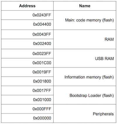
This shows the start and end address for each section of the MSP430’s memory map. There are 148480 memory locations on this microcontroller. How do I know that?
The largest memory address is 0x0243FF. That’s 148479 in decimal.
Because the first memory address is 0, we add 1 to 148479 to get the total number of memory locations.
1 + 148479 = 148480 = number of memory locations
Most of the memory map is occupied by flash, with some RAM as well, along with whatever that “Peripherals” thing is down at the very bottom of memory.
We’ll get to the bottom of what Peripherals are next week!
This post is part of a series. Check out the complete Embedded Software Engineering 101 series here.