Discovery: UARTs Part 2 - Connections
Setting up to use the UART on the F4Discovery DISC1 is a little more complex than just configuring it in Cube and writing some test code. The problem is that there is no hardware connected to the processor so that the UART can be used by your PC.
This week I’ll show you a group of solutions that range in complexity and cost.
What’s the Problem?
When you look at your DISC1 board, you will not find a traditional serial port in the form of a 9-pin D connector and, in your Cube project, you won’t find any default setup information for the UARTs. Since there are 6 UARTs to choose from, and since ST didn’t choose to prepare any of them for use by a PC, we have some work to do.
I think that since UARTs are on their way out, and since the board has USB, ST decided that we can just use a USB UART instead. But USB is a (censored) to get working and you have to add some pretty tricky code.
Solutions
I don’t know what cables you have in your kit, so I’m going to present a wide selection of interfaces.
To get our UART talking to a PC, we have two routes: either convert the UART signal (TTL level) into USB or convert the signal into RS-232.
The USB route
If you are using a serial port for debugging purposes and don’t want to mess around with the RS-232 ports, you could use a UART to USB converter.
The methods I’ll show you are; first, modules that use the ubiquitous FTDI converter chip, and the other uses the debugger processor. These create virtual serial ports that you can use with your favorite terminal program on Windows or screen on macOS or Linux.
FTDI TTL Level Module

Figure 1. The FTDI UART to USB board
The FTDI converter board is nice to have in your kit. This board only needs three wires, transmit, receive, and ground. The module is powered from the USB bus so it doesn’t need power from the processor board.
Even though the pins on the processor can handle 5 volts, it would be prudent to get a converter module that communicated at 3.3 volts. You could use this same module on an ESP-01 WiFi module, but a 5 volt module would destroy the WiFi chip, they do not tolerate 5 volts.
The FTDI converter can plug directly into your USB port on your laptop, but it really is too short and you should use a USB A-A extension cord.
FTDI TTL Level Cable
/MFG_TTL-232R-RPI.jpg)
Figure 2. The FTDI UART to USB cable
Elecia suggested an FTDI cable which does the UART to USB conversion and leaves you with some wires with header sockets. The sockets can be plugged into our board directly, so you don't need jumper wires like in the converter board above.
Like the converter board, only transmit, receive, and ground are needed.
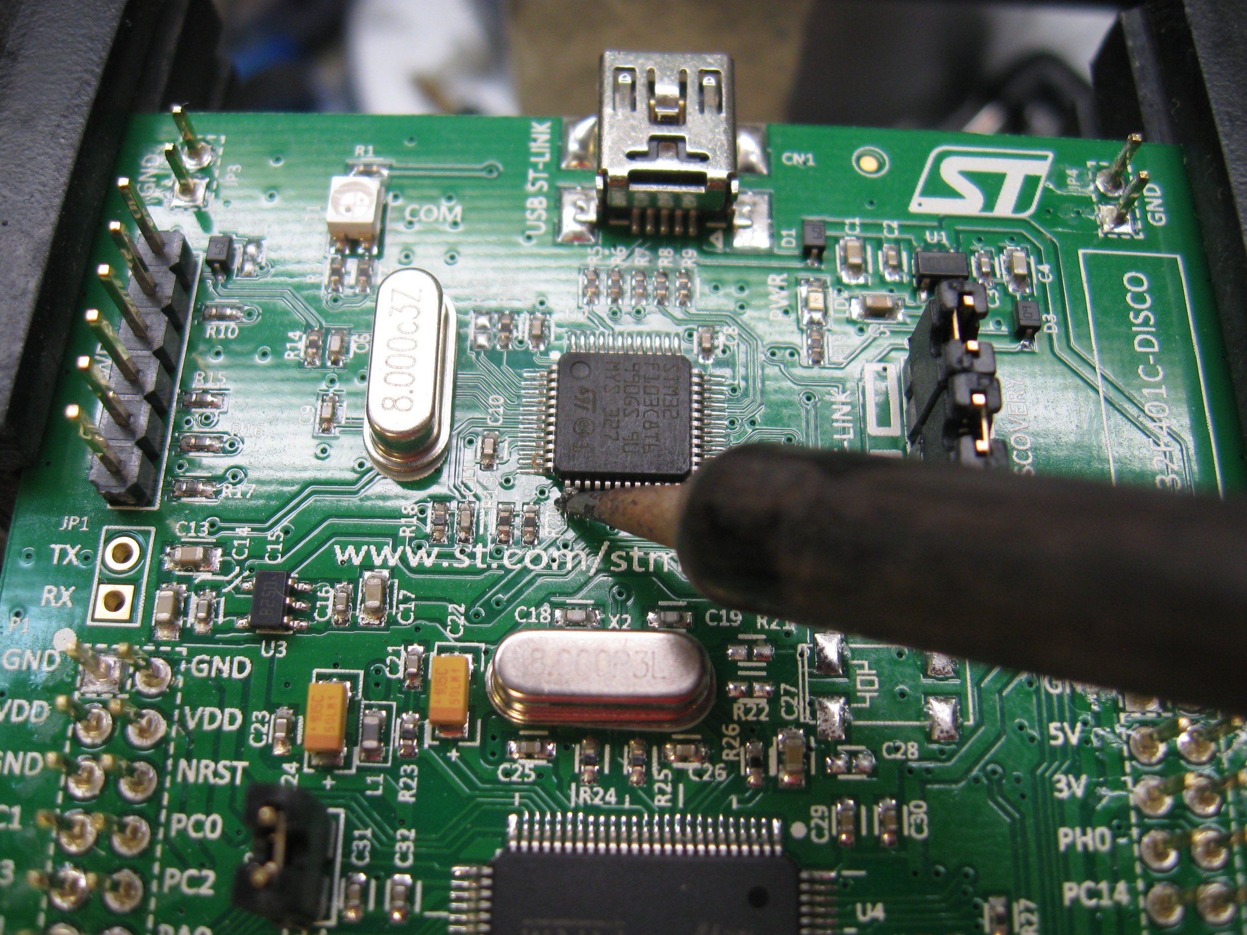
Two Pieces of Wire

Figure 3. Two pieces of wire.
This method is described in the User Manual for the DISC1 board in section 6.13. It involves soldering two wires to the debugger module processor pins.
This method only works if you have the STM32F401G-DISC1 circuit board. The big difference between the DISC1 board and the previous F4Discovery boards is that, on the DISC1 board, ST changed the debug processor to one that supports a virtual serial port. ST didn’t connect the virtual serial port pins to anything, but it has the hardware and software ready to go.
This modification should only be done if you can do fine soldering. Use really fine, single strand, insulated wire, like wire-wrap wire (30AWG).
You can choose any of the 6 UARTs on the processor, I chose UART3 because that is where RTEMS routes their console device by default. To connect to UART3, I have run the black wire from pin 12 of the, smaller, debugger processor to pin PD9 on the bus. The other wire (green? Don't bug me, I'm colourblind) goes from pin 13 to pin PD8 on the bus.
In the documentation, ST wires pins 12 and 13 to bus pins PA3 and PA2 respectively, to hook up UART2. The choice of which UART to hook up is affected by the other peripherals that share the pins, but UART2 or 3 would be a good pick.
The debugger processor method uses the USB cable that you have been using to load your code onto the board. Nice and clean.
The RS-232 route
There are a bunch of UART to RS-232 converters available, but they bring along the baggage of gender changers, null modems, and straight throughs that were the bane of the late 20th century. The cables you’ll need are still available at your local PC parts store if you need to go down this road.
Embest BB

Figure 4. The Embest BB
The DM-STF4DIS-BB also referred to as the STM32F4DIS-BB is an nice little board from Embest Technology Co. that they call a “Base Board”, or BB. This board provides the level shifters and DB9 connector to turn the UART TTL voltage into a proper RS-232 port. But wait - there’s more - there’s also an ethernet transceiver and RJ45 connector, pull-up resistors and micro SD socket, a DCMI camera connector, and LCD connector.
The manual also indicates that SPI, CAN, and I2C ports are also routed to the header pins.

Figure 5. A DISC1 + BB Stack
On the serial connector front, after stacking your F4Discovery or DISC1 board on top, the BB routes UART6 to the DB9, but by removing two shunts and adding a couple of jumper wires, any one of the UARTs can be connected to the DB9.
This board needs a null modem DB9S to DB9S cable to hook it to a PC serial port, or a female to female gender changer to hook it to a RS-232 to USB cable.
For prototyping, this board gives you a lot of convenient ports to speed your projects along.
How Do I Decide?
The FTDI USB module is cheap and small, but it is a bit short and needs a USB extension cable. Elecia’s favourite FTDI USB cable is better choice. It has the length you need and the wires to plug into the bus pins.
If you have the soldering skills, the soldering solution works really well. I soldered up my DISC1 board to take pictures and I love it. No wires hanging out and I can run my board inside of its blister pack.
The Embest BB board is pretty expensive (over $50 Canadian), and isn’t very compelling for use just as a serial port converter, but it brings out a lot of other ports and I’ll be using mine when I start playing with SD cards.
And Finally
We’ve looked at what a UART is, where they are used, and how to get ours hooked up to our PC. Next time we will look at setting them up in Cube and what it takes to communicate.
This post is part of a series. Please see the other posts here.
This week’s music to work by: Tourist - St. Germain