
Discovery: UARTs Part 1
Last time, we look at the LED on our STMicroelectonics F4Discovery board. LEDs are the most basic debugging tool on embedded systems. However, they aren’t very expressive as they can only be on, off, or blinking. You are essentially stuck using Morse code to get your messages out. For communications with machines and humans, we need a proper communications channel. This week we talk the UART.
In this installation, we will be talking about UARTs in general. What are they, how do they work, and the goofy names that are used?
What is Serial?
There are many serial communications devices such as SPI, I2C, I2S, RS-232, USB, and Firewire. Serial indicates that the data is transferred on a single wire, one bit at a time. Contrast this with parallel where all of the bits of a piece of data is transferred simultaneously via many wires.
![SyamilAshri at English Wikibooks [GFDL (http://www.gnu.org/copyleft/fdl.html) or CC BY-SA 3.0 (http://creativecommons.org/licenses/by-sa/3.0)], from Wikimedia Commons](https://images.squarespace-cdn.com/content/v1/50834ba9c4aa1a31c651078b/1480478099718-4SCHTP79Y4RQE6GQFJ35/Parallel_and_Serial_Transmission.gif)
SyamilAshri at English Wikibooks [GFDL (http://www.gnu.org/copyleft/fdl.html) or CC BY-SA 3.0 (http://creativecommons.org/licenses/by-sa/3.0)], from Wikimedia Commons
The advantage of parallel transfers is that all bits are transferred in one cycle. Also, processors internally use parallel transfers, so the data is in the correct form for transmission and reception. The disadvantage is that all of the bits have to arrive at the same time, and as processors get faster and faster, the variation in the arrival time of the bits limit the maximum transfer speed.
Serial transfers have to be converted from parallel to serial, sent out, then converted from serial to parallel, which takes time. But you don’t have to worry about differences in timing of one wire.
UART
The Universal Asynchronous Receiver/Transmitter or UART has been around since the very early 1960s, and have developed over the years. Despite attempts to kill them off, UARTs are still important communications devices in embedded systems.
The UART is the peripheral in the processor that implements medium-distance serial data communication and is the basis of an RS-232 ports on your computer, the small D shaped 9-pin connector. In C, the output from your printf statements often goes to a UART. UARTs are also known as serial ports and are still available on the back of many commodity PC desktop systems.

In its simplest form, a UART uses three pins to communicate; transmit, receive, and ground.
First problem, there is no concept of master and slave in this system, so what does transmit hook up to? That depends; someone who is laying out a circuit board will name the wire (netlist) something like TX, then the system looks like this:

Where the point of view is processor-centric; the processor transmits and receives.
The other way of annotating the circuit is:

Where you always have a transmitter talking to a receiver.
Which way is correct? Your chip or board manufacturer makes that decision for you. I have seen both ways often enough that you really have to read the data sheets to see how each is set up before hooking the pieces together. If I have control over the naming, I will always have transmitters connected to receivers, the netlist method causes so many blown chips. A transmitter connected to another transmitter tends to destroy one or both chips. That is why it is very important to read your documentation and be sure that your transmitters are hooked to receivers.
When you have the transmitter and the receiver on the same board, the transfer is done at processor voltages, a 1 bit being 3.3 volts (on a 3.3 volt processor) and a 0 bit being 0 volts. This isn’t very useful if you are going more than a few inches because, as the length of your traces increase, you start getting distortion and reduced voltages. Eventually the error rate becomes excessive and no data gets through.

Once you leave the protection of the box of your system, some extra chips (buffers) are added to the lines to boost the voltages to give more distance. Now your signals can go many meters without loosing information. The voltages are pretty strange though, a 1 bit is in the -3 to -15 volt range, and a 0 bit is in the +3 to +15 volt range. These are the voltages used in RS-232 communications lines. A great thing about RS-232 is that the buffers also act as current limiters, you can short out these lines and they won’t get destroyed.
Start Data Stop
![By Rs232_oscilloscope_trace.jpg: Ktnbn derivative work: Samuel Tardieu (Rs232_oscilloscope_trace.jpg) [CC SA 1.0 (http://creativecommons.org/licenses/sa/1.0/)], via Wikimedia Common](https://images.squarespace-cdn.com/content/v1/50834ba9c4aa1a31c651078b/1480478473298-5XXTQEVX4TZKPT535SBH/image-asset.jpeg)
By Rs232_oscilloscope_trace.jpg: Ktnbn derivative work: Samuel Tardieu (Rs232_oscilloscope_trace.jpg) [CC SA 1.0 (http://creativecommons.org/licenses/sa/1.0/)], via Wikimedia Common
The UART is a serial interface (it sends and receives characters one bit at a time), but it does not transmit timing information. The sender and the receiver are not synchronized, this is called asynchronous communication. Instead, we use a start bit to indicate when we are starting to send. Then the data is transmitted, and finally a stop bit is transmitted. Ten bits in total.
The bits are transmitted at a prearranged constant rate. The rate that the transfer happens is measured in bits per second, also known as baud. So 9600 baud is 9600 bits per second, and since there are 10 bits per transfer (1 start, 8 data, 1 stop) we get 960 characters per second.
Since the baud rate of a transfer is not transmitted with the data, both parties in the conversation have to know it ahead of time. The clocks on the two systems are not going to match perfectly, but the timing of UART data has enough slop in it that the two systems can have their baud clocks up to 5% off and still be able to resolve the data correctly.
USARTs

A variation of the UART is the USART, the Universal Synchronous/Asynchronous Receiver/Transmitter. A USART has three extra pins, clock, Clear To Send (CTS), and Ready To Send (RTS).
Instead of having a prearranged baud rate, one of the two devices can send out a clock signal, a square wave at the baud frequency. This clock signal is used to synchronize the two devices, getting rid of the need for the devices to have precise baud clocks.
The synchronization clock signal was reasonably common a few decades ago when talking to telecommunications modems. The signal isn’t available on 9-pin RS-232 connectors that was introduced on the IBM PC-AT in 1984.
USARTs support two flow control signals, CTS and RTS, that are used to throttle data flow between the two devices. A receiver may run low on buffer space and, instead of throwing away data, can turn RTS on, saying “hey I’m not ready, please stop”. RTS is connected to CTS on the transmitter, when the transmitter notices that RTS is on, it stops transmitting. Once the receiver processes the data and frees up some buffer space, it will turn RTS off again. The transmitter detects CTS is off and can continue transmitting. This is known as hardware handshaking.
Why would you use a USART instead of a UART? Since the baud clock support is very rare, you would use a USART so you can use hardware handshaking. In code this would require you to either poll the state of CTS or have the CTS pin generate an interrupt,
For compatibility, a USART can be used as a three wire UART, using RX, TX, and ground.
Where Do They Get Used?
Video display terminals are a thing of the past, but there are still devices around that use UARTs. GPS modules, the flash loader port on ATMEL processors, and a lot of industrial equipment still use UARTs.
GPS modules conform to the NMEA 0183 standard, which specifies a UART interface. GPS will be changing over to NMEA 2000, which uses CAN bus, but for now GPS uses UARTs for communication.
Even though you can still get desktop computers with RS-232 ports on them, they are exceedingly rare on laptops. To communicate with industrial equipment and ATMEL processors, like on the Arduino, serial to USB converter chips and cables have kept UARTs alive, at least for a while.
How Many?
Now that we know the difference between a UART and a USART, how many does our processor have? The STM32F407 processor on the F4Discovery board has 4 USARTS and 2 UARTS.
The USARTs are known as USART1, 2, 3, and 6. The UARTs are UART4 and 5. The configuration for them starts on about 1000 pages into the reference manual. It may be easier to use Cube to set them up. We’ll set that up next time, along with configuring the hardware and writing the small amount of code to route the input and output routines to the UART registers.
This post is part of a series. Please see the other posts here.
This week’s music to work by: Water Music - George Frideric Handel
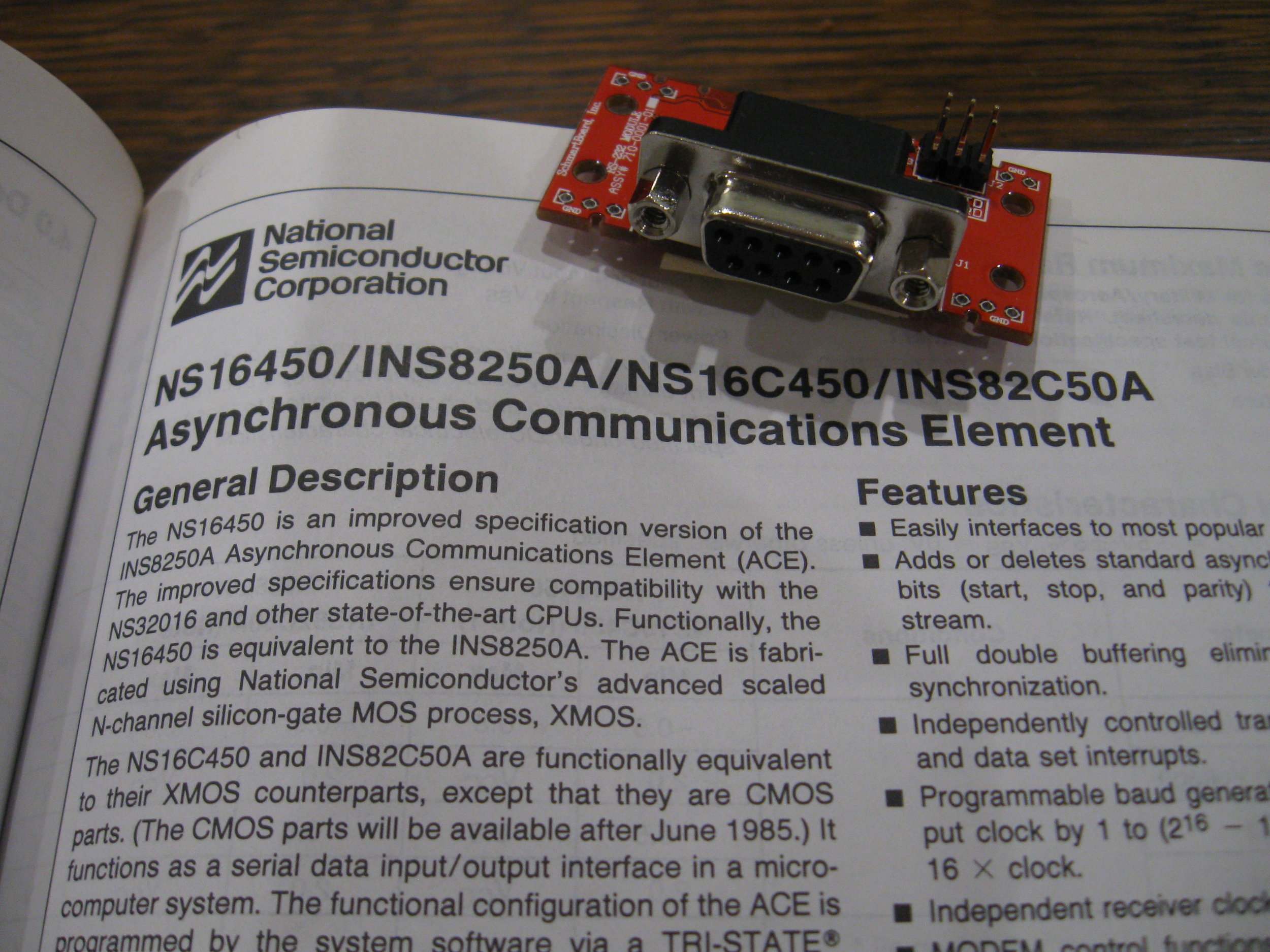
Data sheet for the National Semiconductor NS16450 UART. This extraordinarily popular UART was used in the IBM PC-AT. Also, a TTL to RS-232 converter board from Schmartboard.com.