
Discovery: CubeMX
STM32CubeMX, what the heck, I’m going to just call it Cube, is STMicroelectronics’ software for generating configuration and startup code for their line of Cortex-M processors.
Starting a new project is exciting, until you try configuring the processor. Then the complexity crushes your enthusiasm. Where in the 1400 page data sheet do you look for all of the stupid configuration registers? And which ones are important? That’s where Cube comes in. It starts with a graphical representation of the processor, then helps you get the processor started and the peripherals configured.
Cube serves four purposes: configuring pins, configuring the clocks, configuring peripherals parameters and extra software stacks, and calculating power consumption. Let’s take Cube for a drive and see what each screen does.
Pins
Each year, the chip manufacturers have more and more transistors to use on their new processors. Unlike desktop processors which use these transistors for extra cores and memory cache, microcontrollers load up on peripherals. The dirty little secret is that you cannot use all of the peripherals at the same time because the chip doesn’t actually have enough pins. You've got a problem if you want to use more than one peripheral in a group that shares the same pin.
There are a couple of ways that chips can be laid out to get your peripherals to your pins. First, the chip maker can use something called a crossbar switch which connects pretty much any peripheral signal to pretty much any pin. But crossbars use a lot of transistors that could otherwise be allocated for extra peripherals or memory.
A more common way is to arrange to send the peripheral signal to one of a small number of pins. So when you want to use two different peripherals that share a pin, you can move one of the peripherals to a different pin. The process of discovering the conflicting peripherals and moving them to new pins is a big pain and it must be done before laying out the circuit board.

Figure 1
In my last post, we created a new project in order to force Cube to download the sample code. When we created a project for the F4Discovery board, we were presented with the screen above.
On the left is a list of the peripherals on the processor (an STM32F407VGT6). On the right is a diagram of the processor with some pins already assigned for us, to match the buttons, LEDs, and extra chips on the development board.
One thing to notice: if you look in the top left corner of the chip diagram, and the real chip, you will see a dot. This indicates the position of pin one. Each pin is numbered, starting at pin one on the top of the left side, increasing counterclockwise for 100 pins. Luckily, on the F4Discovery board, all if the pins are brought out to the 0.1 inch headers. The pin names in the diagram are printed next to the corresponding pin in the pin headers, though the order is seemingly random - seek and ye shall find.
As you can see, this processor has a lot of peripherals built in. Some of the peripherals are marked with yellow triangles, and some are marked with red Xs. These are peripherals that have a conflict with the pins that are set up for us.
For instance, the ethernet peripheral (ETH), click on the triangle to the left of the name and it is shown as being disabled. Hover on Disable and it tells us that PC3 is being used by the I2S bus of the audio DAC, and PA7 is being used by the SPI bus to the accelerometer. The peripherals conflict: we’re going to have to avoid using the ethernet and the accelerometer at the same time.
If a pin is grey, it hasn’t been allocated to anything yet. Click on the pin on the processor picture and you will be presented by a long list of things that that pin can do. Any of the pins can be used for digital output (say for an LED called GPIO_Output), or input (a switch GPIO_Input), and many more things. But, for now, take a look at the options.
Clocks

Figure 2
There are two meanings for “clock” when talking about microcontrollers; the clock that tells you the time of day, and the clock that determines how fast your processor runs. The first clock is known as a real time clock (RTC) and this processor has one of those built in. The second is the clock that we are talking about in this section.
Inside of our processor, we have a low precision 16MHz oscillator. You can see it on the left of the diagram above, marked HSI RC (High Speed Internal Resistor Capacitor). This oscillator is made using a resistor/capacitor network and its frequency drifts with temperature, plus it isn’t very accurately 16MHz either. The benefit is that if you were working on a large production quantity device, you can get rid of the size and cost of the external metal can oscillator as long as you can live with the quality of the internal RC.
The F4Discovery board has an 8MHz quartz crystal oscillator mounted on the board. This part precisely generates 8MHz and is far more stable when the temperature changes than the internal oscillator.
In Figure 2, we see that the internal 16MHz HSI RC clock is routed through some selectors and blocks and the processor clock (HCLK) is set at 25MHz. This is accomplished using the goodness of a Phase-Locked Loop (PLL). A PLL is a circuit that takes an input clock signal and can precisely multiply the frequency, taking a low frequency clock and give a higher frequency clock. Other circuitry is attached to divide the frequency down.
The PLL in our circuit takes the 16MHz RC clock divides it by 8, multiplies it by 50, divides that by 4, giving us 25MHz.
Now, through the power of Cube, I want to run my processor at 168MHz (because speed). I have two choices, I can muck around with the PLL, calculating my multipliers and dividers to give me 168MHz, or I can type the number 168 into the HCLK box and hit return. We now get:
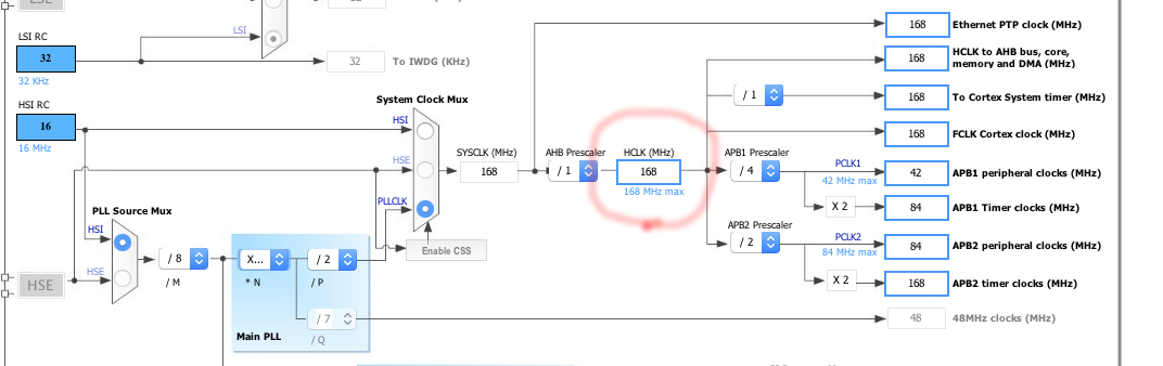
Figure 3
Close enough for now. Cube will generate the configuration code for the Reset and Clock Control (RCC) unit that distributes the clock signals around the chip.
If we want to use the external 8MHz crystal for some more precision, go back to the Pinout tab, click on RCC in the left hand column, and set the High Speed External (HSE) clock input to “Crystal/Ceramic Resonator”. Next, back to the Clock Configuration tab, and set the “PLL Source Mux” to HSE. Finally, put the 168 back into the HCLK box.
The generated code will now set up the processor to use the external 8MHz precision crystal and run the processor at 168MHz.
The clocks also run each of the peripherals (APB1 and APB2 on the right side of Figure 3). One of the really cool features of ARM processors is their low power consumption. They achieve this by turning off the clock to any unused peripherals. When you want to use a peripheral, you need to enable the clock, which is a piece of trivia that often gets forgotten. Luckily, Cube will generate the clock start code when you enable a peripheral.
Setting up the clocks on a new processor is usually a huge pain that involves grokking the clock setup section of the processor manual. Then figuring out how to check all of the settings, usually by getting a serial port working and adjusting things until the baud rate works properly.
Configure
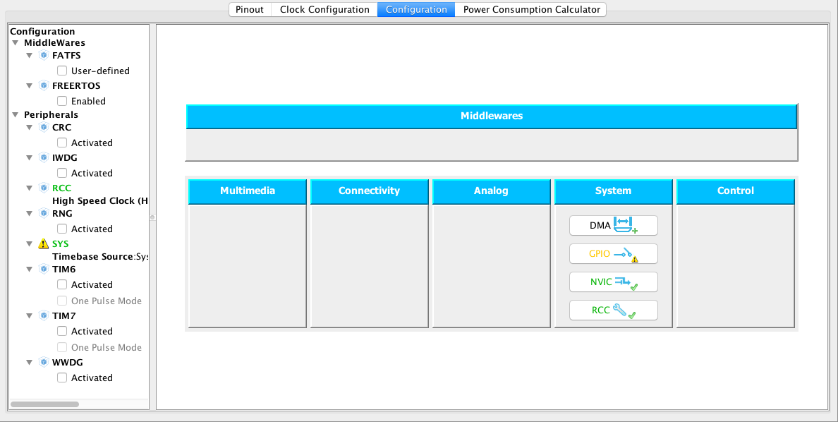
Figure 4
The Configuration tab gives a view of the peripherals that are currently enabled. You can fine tune the parameters of each peripheral and Cube will generate startup and configuration code according to your choices.
The configuration parameters vary, depending on which peripheral you are working with, but include enabling the pull-up or pull-down resistors on any of the GPIO pins, UART baud rates, enabling interrupts, and timer prescalers.
Normally, these parameters are set by depositing values or setting bits in the peripheral configuration registers. Cube takes care of that part, but it also makes sure that the values you set are reasonable.
In the left pane, we see some of the other peripherals that are available that don’t have pins associated to them, as well as two special things at the top. Cube can include the source for the FreeRTOS real-time operating system as well as the FATFS FAT file system from elm-chan.
Power
When working with batteries, minimizing power consumption is really important. Someone will inevitably ask you how long the batteries are going to last, even before you have the program fleshed out. Using the Power Consumption Calculator tab, you can give them a wildly optimistic estimate.
Remember that the processor is only one component on the board that draws current. You may be able to put your processor into deep sleep and draw nano-amps. But if you need to leave an LED illuminated, and it draws 5 milliamps, you’re fighting a losing battle. Energy saving must be applied to every component, turning off power supplies, sensors, clocks, and LEDs.
I haven’t used this screen yet, and it’s pretty advanced stuff, so I will leave exploring this tab to the student as an exercise. (Yes, I hated when my profs would do that, but it’s really not because I’m lazy. Really.)
This gives an overview of Cube. There is a lot there, but next time we’ll see how to generate the startup code and look at a few snippets. In the meantime, make sure your computers are backed up, your laptop might die in the middle of the night and blow the motherboard.
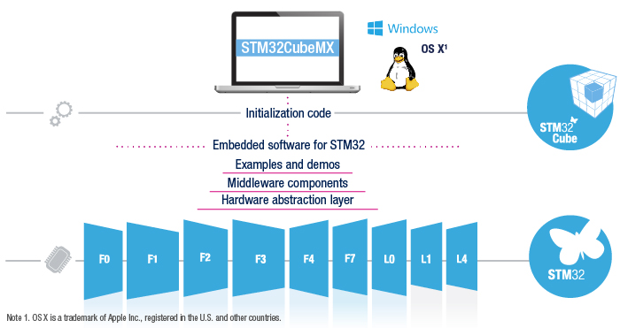
ST's picture depicting the scope of STM32CubeMX.
This post is part of a series. Please see the other posts here.