Embedded Wednesdays: Tools of the Trade
Computers are very stupid, they execute very simple machine code instructions, one at a time, in a strict order, very quickly, and it is up to the programmer to specify each operation, and deviation in excruciating detail (that’s why we get the big bucks). Humans don’t write machine code and computers don’t read English, so we use a pseudo English set of instructions that are converted into machine code. In this installment, we will be using the pseudo English programming language called C.
The tools involved are an editor, compiler, and a loading tool. Combined, these tools are known as your toolchain. When writing a program to run on Windows, Mac, or Linux, you use the tools on the same computer to write your program as you run it. With embedded systems you use a cross compiler on your desktop host computer system and run the firmware on your microcontroller target system. The term cross compiler, implies that we are generating code on one computer system to be run on a different computer system. The whole process looks like this:
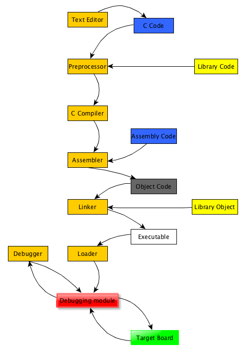
Text editor - To get our C code into a form ready for the next step, we use text editors. Though archaic, we still write our programs as simple text files. No cute formatting allowed. No bolding, italics, page breaks, or UNICODE characters. This requirement dates back to the days of punch cards and teletypes (ask your grandpa) and, unfortunately, there doesn’t seem to be much incentive to change. Even though many programmers’ native language is not English, and we could make our code look cute using script font, or really ugly with Comic Sans, the compiler will trip over the formatting information as errors.
Some people will use Microsoft’s Notepad program for the job, and a lot of code was put together using edlin back in the stone age, but now specialized editors are used that are designed for helping us write programs, for instance vi/vim and emacs. Some text editors are written to help you out by knowing about the syntax of C code, taking care of indenting, and colourizing the various parts of your code, but nothing is added to the program that would mess up the next step.
Microsoft Word is a bad pick for a text editor, it adds a lot of hidden information to your file to give you that “what you see is what you get” look. Although, it may be funny to see what the spell checker does to your code, we’re not working with real English.
What we think of as a compiler takes your C code, from your text editor, and converts it into something that can be executed by a computer. It is made from several cooperating programs; a preprocessor, the actual cross compiler program, an assembler, and a linker.
Some popular C compilers are made by IAR and Keil for ARM and others, Microchip for their PIC processors, Metrowerks for Motorola/Freescale/NXP produced processors, and the free GCC compilers for many families of chips. Let me explain in more detail:
Preprocessor - The preprocessor is used to take our code and prepare it for the compiler. It strips out our comments, brings in extra boilerplate C code, processes macros and replaces the #defines we put in for maintainability and readability.
Compiler - The compiler takes our preprocessor-stripped C code and converts it through a few intermediate steps into assembly code for our target processor. The assembler code is very hard for humans to read, but it expresses what your C code said. The translation between C code and assembly is not simple and the compiler can optimize the code so that it does what you said, but quickly, without wasting resources. The optimizers are very good, they can be trusted, but make debugging somewhat difficult, so they can be turned off.
Assembler - The assembler starts with the theoretically-humanly readable version of the assembly code. This is made up entirely of native instructions for the target processor. The assembler uses it to generate machine code. You can use your editor to write assembly code that is fed directly into the assembler as well. For each C and assembly language file, an object file will be produced. It is in machine code, but the translation is not yet complete. The machine code will have references to data items and functions that haven’t been given a position in memory yet. These incomplete references, or links, are stored in the object file, and are completed by the linkage editor or linker.
Linker - A program is built from many separate fragments of your code and precompiled chunks of library code provided with the compiler. The linker figures out where each piece of code and data will reside in ROM, where each of the variables will live in RAM, then it alters a copy of the object files to fill in all of the incomplete links, then generates the final executable binary file, ready to be loaded into the processor ROM.
Loader - Now that we have our executable file, it must be blasted into our ROM on our microcontroller. The firmware loading program must know about the microcontroller that we are using and the physical connection between our PC host and the target processor board.
The firmware loading program must be told which executable binary file to load and where in the processor to put the file. It then transfers the executable file to the processor, then can read it back to verify that it was transferred properly.
Firmware loading programs are typically included with commercial C compilers or sold with debugging modules. GCC relies on community written loading programs such as OpenOCD.
Debugger - When things go wrong, we use the debugger to run our program, stop it, look at memory, put in breakpoints where the processor will halt just before executing an instruction, run, and restart. We can look at values in memory, and walk our program, seeing the data change and finding out why our program isn’t working properly. Then we can go back to our text editor, fix our code, send it through the preprocessor, compiler, assembler, linker, loader, and start all over again.
Debuggers are either included or sold as extras with your C compiler. GCC relies on gdb as their debugger.
IDE - or Integrated Development Environment. Take all of the items above and bring them together in one program. Write your code, compile it, link it, program your processor, and debug your code, all without changing the look and feel.
This is the current state of the art in embedded firmware production. The modern IDE was borrowed from desktop software development, and modified to include the proper compilers, and a support a debugger that must communicate with a program running on a processor on the end of a cable. Some examples of IDEs are IAR Embedded Workbench, Keil µVision, Microsoft Visual Studio + GCC, TI Code Composer Studio, Atmel Studio, and Eclipse CDT + GCC.
The cost of the various IDEs varies a lot. You can expect to pay $1000 to $6000 for a single user licence for IAR or Keil’s IDEs. They support many different processors and are expected to be used to build commercial products, thus the high prices.
TI and Atmel’s IDEs are free, but can only be used on TI and Atmel processors. TI also restricts the maximum size of your program to 16KB of executable code, after this you have to buy a $495 licence. Atmel does not have a code size restriction.
Eclipse and the GCC toolchain are free, but putting them together can be difficult without good instructions, so your time had better be free. The Eclipse GCC combination support most microcontroller brands, and there are many blogs with instructions on how to put together a toolchain for your chosen microcontroller.
If you have a Windows PC, some random program has probably installed one or more copies of Microsoft Visual Studio on your system already. Check visualgdb.com for more information on how to integrate the GCC toolchain into Visual Studio. I have no experience with this setup (other than dropping Visual Studio the day I first used Eclipse), I’m afraid you’re on your own.
Debugging module - This is the piece of hardware that is used to connect your PC host to the target board. It will go by the name of JTAG, BDM, SDI, SWIM, SWD, or ICD depending on who produced your microcontroller chip. The name indicates the connector that is used to connect to the processor board as well as the communication protocol used to talk to the processor.
When choosing a debug module, you must get one that is compatible with your target processor board. Next, your firmware loading program must know how to communicate with the debug module.
Depending on which target processor board you use, the debugging module may be built on to the board and all you need is a USB cable, or the debugging module might be a separate device ranging in price from a few dollars to thousands of dollars.
My Embedded Wednesdays group at ENTS uses the STM32F401C discovery board from ST Microelectronics. This ARM processor board has a JTAG debugging module attached, add a USB cable and a toolchain and you are ready to begin. The IDE that we are using is Eclipse with the GCC toolchain from the OpenSTM32 project. These tools were chosen to keep costs minimal. I won’t say that they were easy to install, especially on Macs, but they do work.
We are currently investigating the toolchain that our sworn enemy podcaster uses with his Contextual Electronics course. It has a lot of the same toolchain elements but is pre-installed using a virtual Linux machine that runs on your PC or Mac. A couple of people from my group have tried installing the tools on their computers and they show great promise.
Stay tuned for a future article with an overview of the toolchain that we will be using for the second session of Embedded Wednesdays at ENTS.
This post is part of a series. Please see the other posts here.