
Discovery: Button Interrupts
Let Me Interrupt You.
In the first part of our investigation of buttons, we talked about polling the GPIO port to determine if our button was being pushed. The polling code is inserted into your big loop program and it mostly return “button not pressed”, since pushing the button is a rare event in the life of a device. Granted, the device typically has nothing better to do than its normal job plus scan the buttons, but polling can complicate your program. Even when your program gets busy, it still has to poll the button in a timely manner so the button feels right at all times.
There is an alternative to polling; assume that your program is just sitting there calculating the final digit of pi, but you have configured the processor so that when the voltage on the button pin goes from low to high, a function will be invoked automatically which sends a message to Panago to order pizza. This is the idea behind interrupts.
Interrupts act like an asynchronous subroutine call. Whatever your program is currently doing, the processor will complete the current instruction and then jump to a prearranged function. From this function you quickly do some small task and then return. Your program then continues from where it was, but can use the result of the interrupt.
There was no polling necessary, it’s like the button told your program that it got pressed. This is a very powerful feature in computers, but interrupts are one of the more advanced features of the processor. They can be confusing to set up, and since you cannot predict when they will be executed a little more thought is necessary in your programming.
Some Common Program Models
Unlike other forms of software, embedded systems do not avoid infinite loops. Many embedded systems just loop as long as they have power, sampling their sensors and actuating their actuators.
Let’s look at the most common program structures and then see how interrupts change that structure.
Big Loop

The simplest structure for a program in embedded systems is the big loop or superloop. It is an infinite loop where the processing of the system happens each time through the loop.
When you are dealing with multiple peripherals, the big loop model will poll each peripheral each time, or every few times, through the loop. To determine how often to poll, you can use the tick timer or just count loops and poll every N loops. Using the tick timer you get more evenly spaced polling events.
Arduino works with the big loop model, they first call setup() once and then repeatedly call loop(). The infinite loop structure is external to the user code.
Big Loop Plus Interrupts

When using interrupts, your program has a foreground processing section and a background section. The foreground processing is done in the big loop and consists of the calculations to support your system. The background processing is done by the interrupt handlers and is often the data acquisition portion.
Example Interrupts

By Andy Dingley (scanner) - Scan from The Autocar (Thirteenth edition, circa 1935) Autocar Handbook, London: Iliffe & Sons., Public Domain, https://commons.wikimedia.org/w/index.php?curid=15931629, altered using GIMP.
On a car engine management computer, the phase of the engine is determined by a single tooth on the camshaft, generating 1 pulse per 2 engine revolutions. The sensor on the cam generates a pulse train (red) that is fed into the processor. Polling that signal is possible. At high engine speed this signal would come in around 50 times a second and you must not miss any, so you have to oversample (oversampling is where you read (sample) a signal often enough that you are guaranteed to see the signal active pulse more than once in a row). Oversampling is a waste of time, considering that you still have to read the water temperature, exhaust oxygen sensor, throttle position sensor, and do all of the calculations of when to fire the spark plugs and when to open and close the fuel injectors.
If we set up the processor to generate an interrupt on the cam sensor pulse going high, the processor immediately interrupts the big loop processing, does the cam processing, then resumes the big loop from where it left off.
An interrupt can also be generated when the ADC has finished reading the water temperature, oxygen sensor voltage, and throttle position sensor voltage.
In fact, our processor already uses interrupts to give us a millisecond tick timer that we can use for scheduling our polling. Each of our example programs have already been using interrupts.
Hands On Button Example
Create a new CubeMX project for the F4Discovery board, this board is compatible with our DISC1 board but also has the proper entries for the button.
In the Configuration tab, click on the GPIO device. Our button is on pin PA0 with a user label of B1 (Blue PushButton). The first item should be called PA0-WKUP with our user label, click on that line. By default, PA0 is set up to be an input port that generates an event. An event is used to trigger some sort of hardware action like incrementing a counter. We want to change the setting to generate an interrupt. Change the GPIO mode to “External Interrupt Mode with Rising edge trigger detection”. Click Ok.
Next, click on the device called NVIC. The NVIC is ST’s “Nested vectored interrupt controller”. Check the enabled box next to “EXTI line0 Interrupt”. Click Ok.
Now, we can generate our project.
Interrupt Handler
The code that Cube generated uses the hardware abstraction layer (HAL) to remove a lot of the drudgery of setting up interrupts. The HAL has a prearranged set of interrupt handler names that you fill in. Each peripheral has its own set of interrupt handlers and they are documented in the HAL User Manual
All that we have to do is write a function called HAL_GPIO_EXTI_Callback. The HAL takes care of setting up the NVIC; it sets up an interrupt handler that clears the interrupt properly, then calls our routine.
On ARM Cortex processors you don’t have to tell the compiler that your function is an interrupt handler. The Cortex processors just treat interrupt handlers as function calls; the stacking and unstacking of parameters and return addresses is exactly the same as a function call.
Above main() in the file main.c, you have a place for code annotated with a USER CODE BEGIN 0 comment. Place the following code between the BEGIN and END comments:
void HAL_GPIO_EXTI_Callback(uint16_t GPIO_Pin)
{
    HAL_GPIO_TogglePin( LD3_GPIO_Port, LD3_Pin);
}
Compile the code and download it to your board. Hit the black reset button. Now hit the blue button. The orange LED will turn on. Hit the blue button again. The LED will turn off.
Notice that we didn’t put any code into main. The processor is in a very tight while (1) loop, and yet we are toggling the LED on and off without ever reading the state of the button.
My board doesn’t have the debounce capacitor installed, so when I push my blue button, the interrupt handler is called in rapid succession with the rapid on/off/on that is typical of an unhandled button bounce.
WATCH IT!
Interrupts are not magic or particularly difficult, but there are a couple of things to keep in mind when dealing with interrupt handlers.
Shared Data is Volatile
First, if you share data between an interrupt handler and your main line, mark the shared data items as volatile. Volatile is a keyword in C that tells the optimizer to DO WHAT I SAID!
volatile uint16_t portValue = 0U;

void HAL_GPIO_EXTI_Callback(uint16_t GPIO_Pin)
{
    portValue = 42U;
}

void main(void) {
   while (1) {
      if (portValue != 0) {
         munge( portValue);
         portValue = 0U;
      }
   }
}
In this code, if portValue was not marked as volatile, the optimizer would see that portValue can't change in the loop, it only takes the value 0 and never changes. Therefore, it is useless and may be removed along with the whole if structure.
By marking portValue volatile, the optimizer will make no assumptions about portValue and the if code will be run as intended.
This is a common bug when running with the optimizer turned up. If your program acts oddly, try turning the optimiser off (option O0). Your program may now work fine, though it will be bigger and slower. Before turning the optimiser back on, look for shared variables that should be marked volatile.
Let’s Get Critical
Assume that your interrupt handler and big loop share values that are larger than the natural size of the processor (64-bit values on a 32-bit processor). Accesses to this value in your big loop will be made up of two smaller accesses. Even assignment of a value will take multiple instructions.
What would happen if you were in the middle of reading a 64-bit value and you get an interrupt? The interrupt handler executes and changes the value that you are working with. When you return to the big loop you finish reading the value and you are now working with a portion of the old value and a portion of the new value. Corruption! Discord! Chaos!
To avoid this issue, we need to create a critical section. A critical section is a piece of code that must not be interrupted. The critical section is bracketed with commands to disable then reenable the interrupt.
1  volatile uint64_t bigValue = 0LLU;
2
3  void HAL_GPIO_EXTI_Callback(uint16_t GPIO_Pin)
4  {
5     bigValue = 0xFFFFFFFFFFFFFFFFLLU;
6  }
7
8  void main( void) {
9     uint64_t cachedValue;
10
11    while (1) {
12       if (bigValue != 0) {
13          HAL_GPIO_TogglePin( LD3_GPIO_Port, LD3_Pin);
14          bigValue = 0LLU;   // Takes multiple instructions to write bigValue
15       }
16    }
17 }
Karma says that we will take an interrupt in the middle of line 14, which would look like this:
Assign 0 to the low 32-bits of bigValue
*INTERRUPT*
Assign 0xFFFFFFFF to the low 32-bits of bigValue
Assign 0xFFFFFFFF to the high 32-bits of bigValue
*RETURN*
Assign 0 to the high 32-bits
Yielding an answer of 0x00000000FFFFFFFF. Not quite the zero we were expecting. (I can personally assure you that this is real)
There are two things that need to be fixed, the read and the write of bigValue.
while (1) {
   HAL_NVIC_DisableIRQ(EXTI0_IRQn);
   cachedValue = bigValue;   // Takes multiple instructions to read bigValue
   HAL_NVIC_EnableIRQ(EXTI0_IRQn);

   if (cachedValue != 0) {
      HAL_GPIO_TogglePin( LD3_GPIO_Port, LD3_Pin);
      HAL_NVIC_DisableIRQ(EXTI0_IRQn);
      bigValue = 0LLU;   // Takes multiple instructions to write bigValue
      HAL_NVIC_EnableIRQ(EXTI0_IRQn);
  }
Keep It Small
When dealing with a UART, your interrupt handlers could handle the transmitter empty interrupt and feed the next character out of your transmit buffer into the transmitter. On a receiver-full interrupt, your handler could remove the character from the receiver data register and place it into your circular buffer, incrementing the pointer. Polling UARTs that are running at high baud rates doesn’t work well, if you do not poll often enough the UART can shut down because the receive register is full and another character came in. Interrupts work very well until the speeds get very high, in which case you will have to look at the more advanced DMA methods (which I will write about … someday).
When dealing with motors on equipment you may have limit switches, which are physical switches that are placed just beyond the normal limits of travel on a machine, that are used to detect out-of-bounds movements and shut the motors off. These should really electrically disconnect the power to the motor instead of being handled by code. But if you really want to handle it in code, an interrupt generated by the limit switch will be handled immediately, whereas polling has an inherent delay. Your interrupt handler could shut down the motor and leave a notification for the foreground program.
If you are using an RTOS, you will normally program your interrupt handlers to send a message to a task in your system with the incoming data or some sort of flag.
… And In Conclusion
Next time we will look at the UART so we can get a little more feedback from our board than just blinking the LEDs.
This post is part of a series. Please see the other posts here.
This week’s music to work by: Dave Brubeck Quartet - Jazz Goes to College on Columbia Jazz
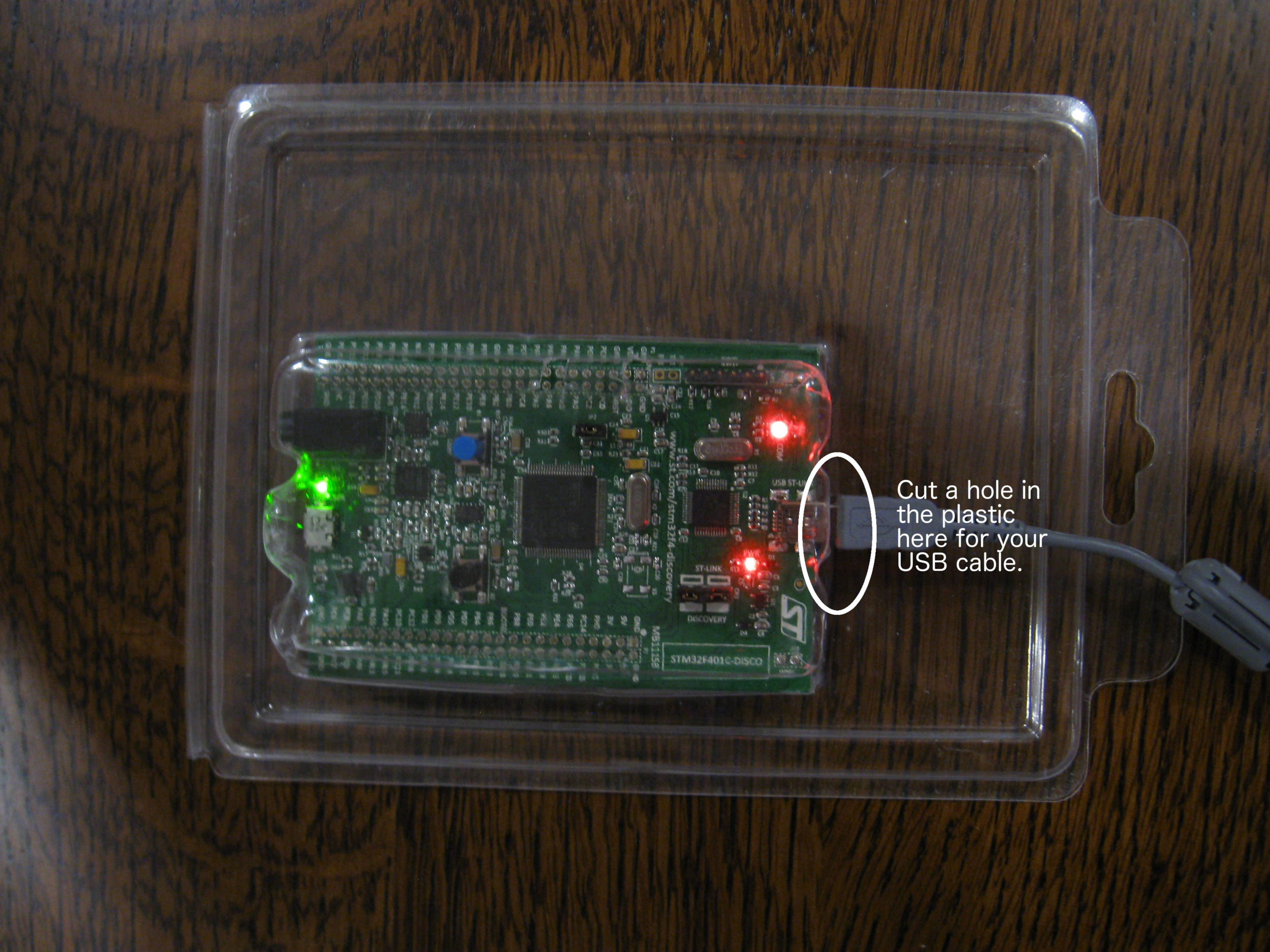
There’s a reason that I suggested that you keep your packaging.