
I Apply SPI: Good Vibrations
The last few posts in this series have covered the fundamentals of the SPI interface, background information about reading schematics, oscilloscope traces, timing charts, and data sheets.
The last post used CubeMX to configure our development board. The process would be generally the same if you were using a different processor: find the important parameters in the data sheets, the associated registers in the processor, and set the configuration bits to match. CubeMX is convenient, but the process is the same.
In this post, we’ll be taking a look at the firmware involved in using SPI. We’ll be using ST’s hardware abstraction library (HAL). We will start at the bottom, with the basic function calls to control the select pin then send out some data via the SPI bus. Next, we look at the form and specifics of the command structure for an accelerometer. Finally, we get some data flowing.
Starting Up
The peripheral chip that we will be communicating with is an ST Microelectronics LIS3DSH three axis accelerometer. This chip is configurable to read +/-2, 4, 6, 8, or 16G acceleration in 3 dimensions at a frequency of 1Hz to 5kHz. The output data is presented as signed 16-bit values (int16_t).
From last week’s post, we have some startup code to initialize the processor and the SPI bus. The two data lines, clock, and select line are configured and have been initialized.
If you are not using CubeMX, the first order of business is to de-select the accelerometer.
HAL_GPIO_WritePin( CS_PORT, CS_PIN, GPIO_PIN_SET);
The HAL routines for the general purpose I/O pins (GPIO) use set and reset to indicate the output level on the pin. Set means high (1/on), and reset means low (0/off).
First Light
Now that we’ve got the processor configured, to send data over the SPI bus, we have to select the slave chip, simultaneously send a request and receive a result, then de-select the slave chip.
First, remember that the accelerometer datasheet showed that we need to make the chip select (CS) line go low to select the chip. To make select go low, we use the code to reset the GPIO:
HAL_GPIO_WritePin( CS_I2C_SPI_GPIO_Port, CS_I2C_SPI_Pin, GPIO_PIN_RESET);
Then we send the data to the SPI bus. We have a handle from the initialization code (hspi1). The idea is that we have an array of bytes that we send out on the MOSI (master out) GPIO line. This is the transmit buffer. We get another array back from MISO (master in) GPIO line at the same time, and want it in the receive buffer. And the final parameter is the number of milliseconds to wait for the transfers to happen before we get a timeout, in this case 100 milliseconds.
status = HAL_SPI_TransmitReceive( &hspi1, transmit, receive, length, 100);
Then we deselect the slave:
HAL_GPIO_WritePin( CS_I2C_SPI_GPIO_Port, CS_I2C_SPI_Pin, GPIO_PIN_SET);
Bringing it all together, we now have a generic function to send out an array of data and get the results back:
void SPISend(uint8_t* transmit, uint8_t* receive, uint16_t length) {
   HAL_StatusTypeDef status;

   HAL_GPIO_WritePin( CS_I2C_SPI_GPIO_Port, CS_I2C_SPI_Pin, GPIO_PIN_RESET);
   status = HAL_SPI_TransmitReceive( &hspi1, transmit, receive, length, 100);
   HAL_GPIO_WritePin( CS_I2C_SPI_GPIO_Port, CS_I2C_SPI_Pin, GPIO_PIN_SET);

   if (status != HAL_OK) {
      printf("There is a problem with the SPI transmit %d\r\n", status);
   }
}
Up A Level
We are finally at the abstraction level where we need to know the details of the accelerometer command structure.
In the accelerometer data sheet, is a timing chart for the SPI communication.

Where SDI shows the data coming out of the master and SDO shows the data coming out of the slave.
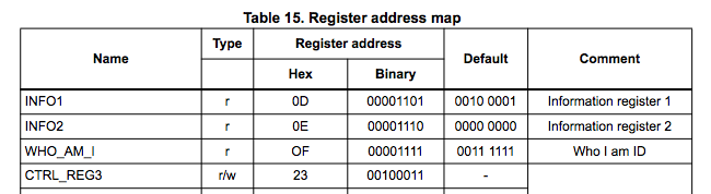
The accelerometer appears as if it is a bank of registers that can be read or written. The master sends out one 8-bit value, the first bit being a read/write indicator, the second bit being an indicator I ended up ignoring (more on that later), and the next 6 bits being the register number of the value that you are interested in accessing. Meanwhile, the slave values coming back from the accelerometer are ignored by the master since the diagram in the data sheet indicates that they contain no useful information.
The next 8-bit value coming out of the master are not used by the slave during a read operation, and the slave will reply with the value of the register.
This gives a waveform that looks like this:

Channel 1 (yellow) is select. Channel 2 (cyan) is clock. Channel 3 (magenta) is SDO. Channel 4 (green) is SDI.
Across the bottom we see chip select go low (on the left), and later (right) go high, that is the full transfer operation. One trace up, we see the clock providing a total of 16 low going pulses, the pause between the two bursts of 8 pulses does not upset the transfer. SDO or Master Out Slave In (MOSI) is on the top. We see the request being sent out (from left to right) in the first set of 8 clock pulses. Master In Slave Out (MISO) is next down, it has a bit of noise while the master is talking (ignorable), and it transmits during the second set of 8 clock pulses.
My oscilloscope can decode SPI communication, showing the simultaneous MOSI and MISO values. Decoded it looks like this:

Now, what are these values anyway? The commands are documented In the accelerometer data sheet.
. . .

The first value of MOSI is 0xA8, which is an access of register 0x28 with the read bit set. We are reading OUT_X_L, the low byte of the X axis reading. The C code to do this is:
transmitData[0] = (uint8_t) (LIS3DSH_READ |  LIS3DSH_X_L);
transmitData[1] = (uint8_t) DUMMY;
SPISend( transmitData, receiveData, 2);
xl = receiveData[1];
Details Details
The accelerometer has a few configuration registers that need to be set up before you can retrieve any data. In the code below, I have included a reasonably typical group of settings gleaned from various sources. One important flag is LIS3DSH_CTRL_REG4_BDU. This flag tells the accelerometer to inhibit changes in the accelerometer readings until both the upper and lower bytes have both been read. Without this bit, you could read one byte and, in the time between reads, the acceleration could change so that the previous byte is now wrong.
The accelerometer has 16-bit resolution, which is really sensitive, so the values bounce around a bunch.
Here is my test code (create a project in Cube and just before the infinite loop in main.c, call Application()). Once you get it running, tilt your board to see the values change. The main acceleration felt by the board, while it sits on your desk, will be gravity so you should see 1 G downward, represented as about 16000 counts.
Now, where did that number come from? The data is represented as a signed 16-bit number, having a range of -32768 to 32767. The accelerometer (in the code below) is initialized to have a span of +/- 2G. Gravity gives us 1G, so the readings should be about ½ of full range. When I flip my board around I get values of -16K or 16K in the X and Y directions, but Z (zed) seems to have a bias of a couple of thousand counts. Does yours?
The accelerometer orientation on the board isn’t documented, so you will have to look at the values change as you tip your board.
After a lot of debugging, I figured out that there are some significant errors in the datasheet for the accelerometer. It turns out that the poorly documented multiple/single (M/S) bit doesn’t actually exist, and that all you have to do to read out multiple registers back to back, is to do a multi-byte read:
transmitData[0] = (uint8_t) (LIS3DSH_READ |  LIS3DSH_X_L);
SPISend( transmitData, receiveData, 7);
x = (int16_t) (receiveData[2] << 8) | (int16_t) receiveData[1];
y = (int16_t) (receiveData[4] << 8) | (int16_t) receiveData[3];
z = (int16_t) (receiveData[6] << 8) | (int16_t) receiveData[5];
More More More
What would you use an accelerometer for in an embedded system? The phone makers use accelerometers to reorient your screen automatically. Your fitness tracker uses them to count steps. Disk drives use them to detect that you have dropped your laptop so, while in freefall, the disk drive will retract the heads to avoid scratching the platters. And if you read through the data sheet, you’ll find that this accelerometer can also generate an interrupt when it detects gestures like tap and double-tap. How cool is that?
Okay, that’s it for SPI. You’ve gotten the background material on reading oscilloscopes, schematics, and timing charts. You have the essentials of how Select, Clock, MOSI, and MISO interact to transfer data. We’ve set up a project in Cube and found out all of the ways that the data sheets conspire to never call anything Select, Clock, MOSI, or MISO. And we’ve got an accelerometer showing us which way is up.
We’ll draw on this information when we look at the I2C bus soon. Stay tuned.
This post is part of a series. Please see the other posts here.

Music to work by: Synergy - Semi-conductor a best-of album from Larry Fast.