
Karaoke's Disco Lights
The karaoke has four blue LEDs and six red LEDs (shown from the outside of the toy in Figure 2-7), and they’re controlled by only three pins. One of the pins provides power. For some fancier, more expensive systems, that could mean that the LEDs have some intelligence to them using some sort of serial communication, a topic for another chapter. But for the karaoke, it is a cost cutting measure: running fewer wires is cheaper. The LEDs marked with “1” turn on together and the LEDs marked “2” turn on together.
Figure 2-7: The karaoke’s front with the LEDs marked according to when they light up.
Inside the Karaoke
Tearing apart the karaoke was somewhat terrifying. There are many components, held together with wires soldered onto boards. Of course, the wires are as short as possible so moving them is difficult. Anyway, it quickly became clear that I would have to be very careful or I’d never get it working and/or back together. Figure 2-8 shows the karaoke parts, not quite in a pile.
Figure 2-8: Karaoke will go back together someday. To do that, I will need this picture plus the 30 others, some with post-it notes.
The LEDs that are on the front of the system, the ones I want to look at further, are on the bottom of the image in Figure 2-8. In Figure 2-9, I took pictures of both sides so you can see what I mean about wires soldered to boards.
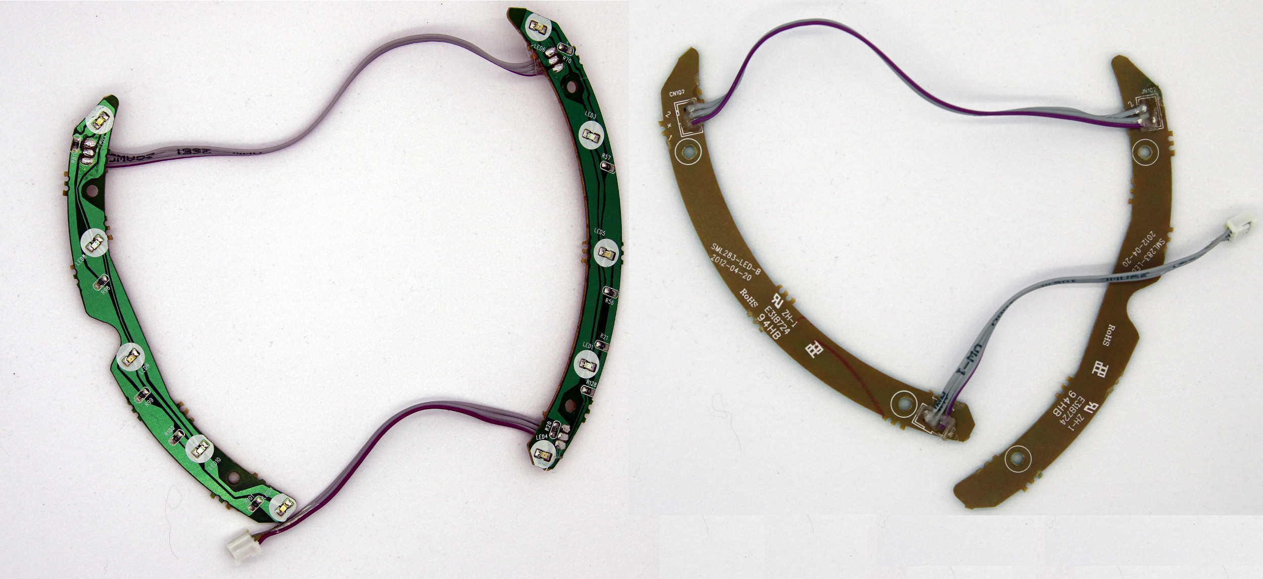
Figure 2-9: Both sides of the karaoke's disco LED boards.
Note that one side is green. It has the LED and resistor components and the shiny traces. The traces are the physical connections between parts. The other side of the board is brown and has letters (the same silkscreen we saw earlier). This is a single-sided board; everything electrical happens on the green side.
Figure 2-10 shows the circuit. While I used beep mode to be sure about some connections, for the most part, I could trace the circuit with my eye. There are three wires going to the LED boards. The spot where the wires attach to the board is marked “1 + 2”. The center wire is power, shared by both the 1 and 2 strands. The control line (1 or 2) is grounded when the system wants the LEDs lit.
Figure 2-10: The karaoke LED circuit board (left) only has three wires going into it. The drawings at right show the circuit schematic.
LEDs in Parallel
Unlike BB-8’s RGB LEDs, the karaoke LEDs are not in series. Instead, they are connected in parallel, most easily shown in the rightmost circuit in Figure 2-10. When LEDs are in series, each one in the chain gets a little less voltage than the one before it (the ones closer to the battery get more).
With the red LEDs, this doesn't matter, the voltage drop over each LED isn't very big. But the blue LEDs require a little more voltage than the red ones do (this is a property of the LEDs, part of how they are made). Running the reds and blues in parallel keeps them all at the same brightness, as each LED has the same voltage across it.
As expected, each LED is connected to a resistor; each resistor is 100 ohms. However, unlike current limiting resistors in circuits where lots of power is available, these resistors help balance the load of the LEDs in parallel. They are called ballast resistors. Without them, normal and slight variations in individual LEDs might make one LED have more or less resistance than others. Even if an LED starts with only marginally less resistance due to some tiny chance difference in manufacturing, more current can flow through it, making it brighter than the others and burning it out a little. Each time the LED burns a bit, it will have less resistance, until the LED burns out entirely. The ballast resistors equalize the paths of the circuit.
One Resistor Would Be Cheaper
Engineering is often a balance between functionality and cost. As a whole, the karaoke is made more cheaply than the other toys in this book. Instead of connecting the LEDs in parallel, the designer could have used a series chain of LEDs and a single current limiting resistor. This would have reduced the number of parts, allowed the board to be smaller, and been cheaper to make. However, resistors cost very little, and units would have been returned if one bad LED caused all of the other LEDs in the strand to go dark like cheap Christmas lights. Calls like this come up often when designing electronics for mass production, and as you investigate more toys, you’ll definitely find more circuits where functionality won out over cost.
Going further
Toys use LEDs to interact with users in all sorts of ways; LED circuits behind those interactions can vary just as much. The karaoke has LEDs in parallel so they are consistently bright. BB8 has a simple blue taillight that is controlled from a processor and draws current from a MOSFET transistor, keeping it bright even if the processor can’t drive it directly. BB8 also has RGB LEDs in the same transistor configuration, but there are two RGB LED in series, always in sync. The quadcopter controller has a big LED whose voltage is greater than the battery’s.
All of these LEDs have an important thing in common: they blink! Often the very first thing I will do when I have a new board to try out is to blink an LED to prove that my code is running.
Blinking an LED isn’t very difficult. Arduino UNO, an inexpensive microprocessor board, is ubiquitous and designed to be easy to setup and use. Or you can try out BB8’s processor with an ST development board (NUCLEO-F334R8). It works with the free, online compiler called mbed (which has many, many examples). Both of these will have you blinking their on-board LEDs in no time. Whether you decide to try out building more complex LED circuits is up to you.
If you’d like to dig deeper into the electronics: my favorite books are The Manga Guide to Electricity and Forrest Mims’ Getting Started with Electronics.
Next week, we graduate from lights to buttons!
This is a series. If you’d like to read them in order, check out the Taking Apart Toys index.