
Hand Waving and OpenCV
I like being able to explain what I’m doing. I like knowing something all the way down to first principles. I like how the depth can inform the explanation. But…. I also like getting things done. Working on Ty, the typing robot, it seems like I have to keep switching back and forth between surface learning and depth. The perspective change is giving me vertigo.
Having determined that pressing keys with a fixed calibration won’t work, I wanted to start using camera feedback. It makes sense: humans learn to type through visual feedback. It should be no problem to put that in a robot. Nope. Not a problem. Not at all.
Ok, so, I have no idea how to do that. I am in the vigorous hand waving stage of this project. The number of things I don’t know how to do far exceeds the number of things I do know.
Trying to break apart the problem doesn’t leave me with a path to follow. How am I going to teach the system to find a keyboard with the camera? I’m not going to create a rigid system that only works on my desk so that means the camera angle will be variable. How am I going to find a keyboard when the camera can be at different angles? How do I find the keys in the image? How am I going to translate that into positions for the robot? How am I going to figure out the arm’s calibration for a given session? Can I find the arm in the image to fine-tune the motor control? What other questions should I consider that I don’t know exist?

OpenCV2: Finding the Keyboard via Camera
Happily, I came across a book, Learning OpenCV 3. To be fair, the book is quite similar to the open source documentation for OpenCV computer vision library (for Python and C++). I had already read the first few chapters of the online tutorials a number of times. I used the color space and object tracking section for laser finding for Ty. This time, I skipped over a bunch of face-finding nonsense, flipping through the pages of the book, I found a tutorial about feature detection that seemed really interesting.
I found points of interest, mostly corners, with SIFT. I matched the points of interest with FLANN. I used homography to determine a transform from my perfect keyboard to the real-life in-image keyboard. Let me be honest here: I don’t know what SIFT, FLANN, or homography are. I can not explain more than their function calls and applications. I can’t show you the math on why they work. There are parameters but I don’t know if, or how, I should tune them, I just hope the defaults continue to work.
And they do work! Given a master query image of a keyboard, the magic Open CV2 code finds the keyboard in my frame, returning a matrix I can use to transform between my master keyboard and the real life keyboard.
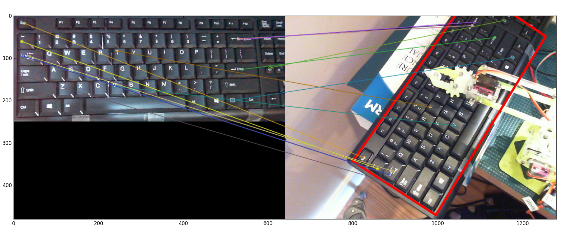
I’m skimming along on the surface of computer vision, failing entirely to grasp any depth. It is unsatisfying to live in continued ignorance. On the other hand, it makes for pretty pictures. And the pictures sort of explain what the algorithms are doing: mapping from my master keyboard (left) to the actual keyboard (right).
This worked so quickly and brilliantly that I was a bit taken aback. It was too easy. I felt like I shouldn’t use something so obviously complicated that I didn’t understand. Of course, if I felt like that all the time, I’d never drive a car.
If you want to see the code, it is in github. Where the laser-chasing cat is under laser_cat_demo, the code for this is in prototyper. To run the homography piece:
nvidia@tegra-ubuntu:~/Ty/TyPEpyt/prototyper$ python
Python 2.7.12 (default, Nov 20 2017, 18:23:56)
[GCC 5.4.0 20160609] on linux2
Type "help", "copyright", "credits" or "license" for more information.
>>> execfile('TyKey.py')
Point [ 334.71691895  123.89203644] is key ['j']
>>> k.kvm()
Point [ 334.71691895  123.89203644] is key ['j']
As you run it, each call to k.kvm() will show the current video stream from your chosen camera. Once you have the keyboard fully in frame, with your mouse, click on a letter on the keyboard. The code will run the homography functions and then use the mouse click location and transform to determine the key. For that to work, I had to give the coordinates of each key from my master keyboard image.
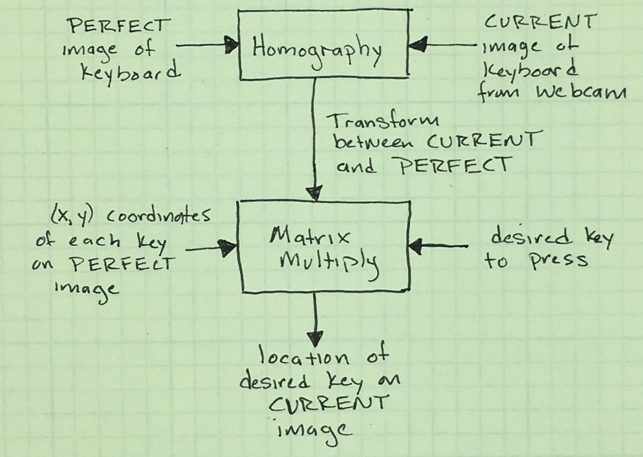
I like being able to find the keys using mouse clicks. But that is backward from my goal: to find the coordinate of the key I want the arm to type. Happily, the transform just needs to be inverted (matrix inversion is a pain if you do it by hand, so yay for computers). What I get is a fairly simple process to turn the desired key into a location on my current webcam image.
Now that I can find the keyboard in the camera image, I need to find the arm in the same image. Then I can tell the arm where it needs to go.
Finding the Arm
I thought the homography was a neat trick that seemed too easy. On the other hand, finding the arm was an order of magnitude more difficult than I expected. I mean, I already accomplished object tracking with the laser, how hard could it be to find a bright yellow arm?
Realistically, I don’t want to find the whole arm, just where the gripper is holding the tooth made of hot water moldable plastic. In technical terms, this is the robot’s end effector.
I put a red, glittery happy face sticker on the tooth and tried out my red-dot finding code. It didn’t work at all, the change in lighting caused all sorts of problems with the glitter effects. I tried other stickers and got frustrated that they didn’t work consistently. I returned to the OpenCV book, hoping that skimming it would give me an idea. Sure enough! There is a function called Hough Circle Transform (wiki, CV2 doc). The parameters were inscrutable. Don’t believe me? Well, here is some of their documentation:
- dp: Inverse ratio of the accumulator resolution to the image resolution. For example, if dp=1, the accumulator has the same resolution as the input image. If dp=2, the accumulator has half as big width and height.
- param1: the higher threshold of the two passed to the Canny edge detector (the lower one is twice smaller).
- param2: the accumulator threshold for the circle centers at the detection stage. The smaller it is, the more false circles may be detected. Circles, corresponding to the larger accumulator values, will be returned first.
But it worked like a charm in the tutorial, placing an OpenCV drawn-circle around the identified one in the image. Sometimes it worked like a charm for me.
The Hough Circle transform returns the center and radius of each circle it finds. With that information, I drew a green outline circle around any red circles it found:

Other times, it would fail miserably, drawing new circles to identify found circles that existed only in its delirium. Worse, it didn’t even find the actual red circle sticker, instead just drawing junk all over.

This is a magical incantation and I’m clearly not a wizard. Oh, I tried different parameters but nothing consistently worked. It was frustrating because I could so clearly see the circle I wanted in the image and couldn’t understand all of the spurious, obviously non-circular circles the transform was finding. I tried different circular stickers, hoping for better results.

CIRCLE ALL THE THINGS!
Finally, I gave up trying all the things. I had to read more: more than the documentation, more than the Wikipedia page. I read the code. (Gasp!)
I found the clue I needed (which, to be fair, was in the documentation of those parameters I found inscrutable). The Hough Circle Transform depends on the Canny edge detector. The Canny edge detector was something I saw in Udacity’s Self-Driving Car term 1; it finds the edges of objects in an image. The image needs to be grayscale, ideally with only the detail you really want found.
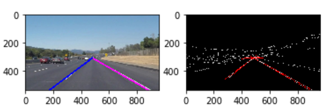
For example, as part of a lane-finding project, I started with an image (left, without the bright lines overlaying the lane markers). I smoothed that to grayscale, smoothed it, did a Canny edge detection (shown below on the right, in black and white). From there, finding straight lines was fairly straightforward (right, red). I could then find lines of interest and plot them on my original image (left, blue and pink). If you'd like a better explanation, Chris Svec's lane-finding project has a better write-up than mine did.
Back to the robot arm: even though I could see the circle very clearly in grayscale, the view in Canny space was exceptionally cluttered.

In this view, I look at the Canny edge detection of the image (upper left), again after I blur the image (upper right), and the resulting Hough Circle Transform. This made me realize why the circle finder was giving so many spurious hits: its input was too noisy. The next step was to significantly decrease the information getting to the edge detection process.
I started by choosing a sticker that was not glittery (sad) and was a blue color not found otherwise in my image (red stickers and red cables fought a bit in the image). I switched the colorspace from being represented as RGB to HSV as this let me filter on the hue of blue without worrying about lighting changes. Then, I filtered out everything except the color of my sticker. I boosted the remaining signal (dilate), blurred it to get rid of noise (blur), then again boosted the remaining signal (dilate). No longer did the edge detection stage have any problems finding circles.

I suppose I could have simply found the centroid of the shape in the dilated image (upper right). But I wanted to limit the difficulty of finding circles in the case of real image noise. Of course, this is sensitive to other objects that are the right shade of blue. Using the circle finding limits the errors.

Since the Hough Circle Transform gives me the center of the circle (and its radius). By placing the sticker over the end effector, I get the position of the part of the arm that will press the buttons. The code is straightforward to run. After the "execfile('TyKey.py')" above, you can call
>>> k.locateClaw(showDebug=True)
Frame not passed in.
There are  3  originally,  1  good ones:  [array([212, 192,   3], dtype=uint16)]
The debug messages indicate that without a frame passed in, the code should use the camera. It notes that 3 circles were found but only one in the area of keyboard. Then it gives the location (212, 192). Note: you can also re-run k.kvm() which calls k.locateClaw().
Summary
I have laid this out to be somewhat logical, showing only a few error paths. Don’t think that it all happened in an orderly fashion. This was a pain. But now it works almost all the time.
I disliked the magic of homography but I really enjoyed getting things done so fast. I disliked the pain of getting the Hough Circle Transform to work but I feel good knowing I understand it thoroughly.
I want to learn, that is the real goal of the project. But how much do I need to understand and how much do I simply need to learn to use? Honestly, I don’t know. I suspect I never will.
But now I need to apply all of this to controlling the motor. I know the key I want to press and use the homography to find the location on the camera image, how does that translate to the x,y of the arm? And given the arm moves where I tell it but the camera shows it isn’t over the desired key, how do I get the arm to budge over in the right direction? I suspect I’ll need to start with a diagram...