
Completely Lacking Sense
I have spent weeks working on my typing robot (Ty). I have been studying a Reinforcement Learning textbook (and also studying the math that goes along with it, looking up things on Wiikipedia, and reviewing my old control theory textbooks because some of these concepts are eerily familiar).
Other than giving myself some headaches and learning some things, I feel like I haven’t made any progress. Worse, after deciding to try a more tactical approach, I think my plan for using reinforcement learning to have Ty find keys on different keyboards is untenable. That’s not what reinforcement learning is for… or it would take a hundred years to train my arm on each new keyboard.
Monitor the Current from Servos
Disappointed, I decided to do something I was more comfortable with: use an ADC to monitor the servo current draw. With current monitoring, I could see when the motors are stuck and either move them back to safety or cut power to them entirely. With a little bit of fancy code, I could likely identify when the shoulder/elbow parts of the arm were struggling with gravity and let them come at the target position from a higher position. (So that they rise with high torque then fall into place instead of struggle for the last few millimeters at low torque.)
In my head, this is easy. Four servos means four current sense resistors going into my four channel ADC (ADS1115). It can share the I2C bus with the PWM Servo Driver board (PCA9685) since that isn’t really heavily trafficked. I even have a sketch for how to lay it out so the breadboard is reasonably untangled.
I used this “Making Embedded Systems” book to remind me how to use a resistor to monitor current:

That figure shows high-side current measurement but I know low-side current measurement is also possible (where you put the resistor in series with the system but on the ground side). There are advantages to each but I don’t care, my needs for this measurement are fairly gross. I don’t care if it is drawing 0.01 A or 0.02 A, I want to know if a servo is consuming 0.1 A, 0.2 A, or 2 A. So my plan looks like this, with a low-side current measurement configuration:

What Is the Resistance?
But what should the resistor value be between the servo ground and the system ground? Even though my motor is powered at 5V (V+), the ADC is going to run at 3.3V.
Ohm’s law (V=IR) says that if the expected current is 1 A and the max voltage for that current is 3.3 V, then R = 3.3 V / 1 A = 3.3 ohm. Wow. That’s not much. But ok.
Past experience has burned into me that I need to check the wattage too:
P = V * I so 3.3 V * 1 A = 3.3 W
Digikey has resistors that meet or exceed these values. And maybe there is some in the big bag of resistors in the garage. (Yes, it is a bag of resistors. It is not well organized. You stick your hand in and a combinatorics problem appears. I ended up vacuuming the garage to get through the spiders to get to the resistors. By the time I got to the bag, I was happy to find anything in vaguely the right range.)
Given my “ehn, close enough” resistor values, I wanted to try them to see if this would work at all, starting with an oscilloscope. I’m not 100% sure what will happen with the PWMing so let’s put the circuit together and try it out. However, the more I looked at my circuit plan the more it looked like a current limiting resistor on an LED circuit:

Is that right? That doesn’t seem right. Can you use one circuit for more than one thing? I don’t think so. I mean, can you?
Listen, I just finished with a bunch of stuff I didn’t understand and tried to learn enough to follow the simple examples and you can’t make me learn electronics too, I’ve already tried to learn that and I finally understand FETs and I think that’s enough, don’t you?
<...time passes...>
Whew. Somebody needed a nap.
Let's Try It and See What Happens
Sometimes the easiest way to learn about stuff is to try it.
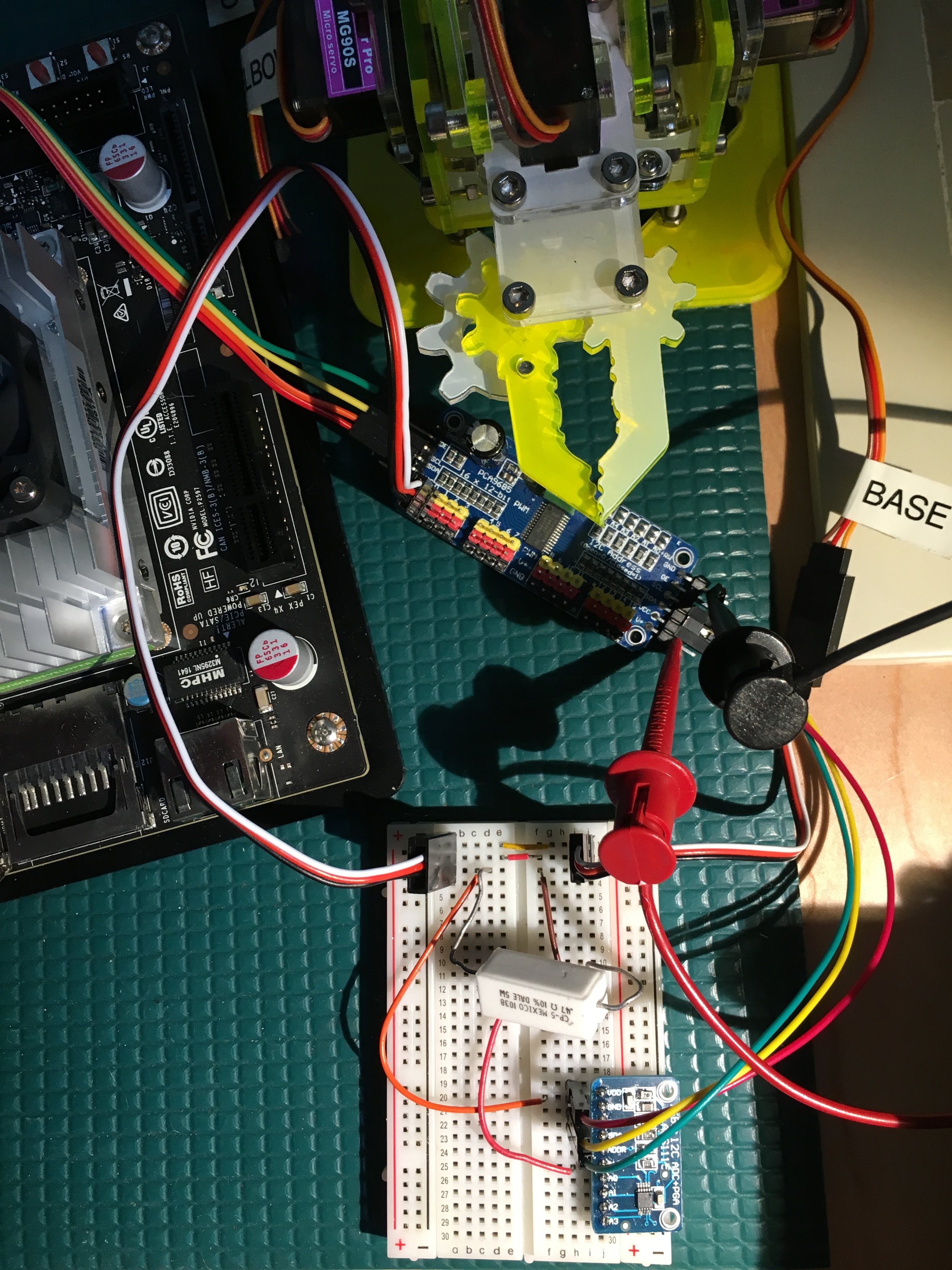
From the spiders in the garage, I have a 0.47 ohm resistor (5W) in series with one of my servos (the one that turns from the base). Let’s see what this looks like an oscilloscope if I hook the scope probe up to ADC measuring point (at the servo ground, before the resistor). I hook the scope ground to the system ground (after the resistor). Like this:

When the motor is holding steady with no effort (0.003 A on the power supply), I see a pretty boring picture:
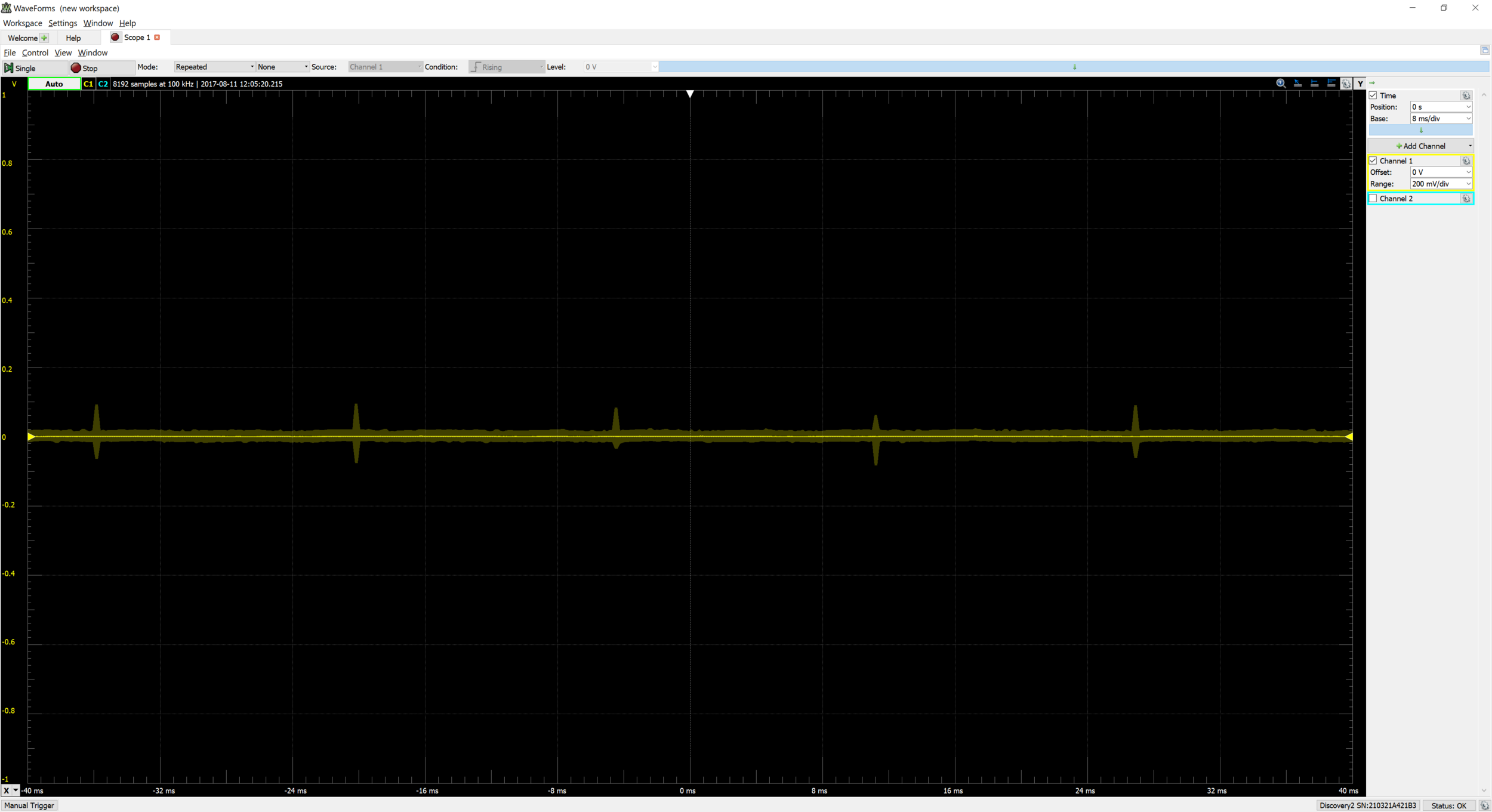
If I hold the motor a little off its destination so that the power supply shows about 0.1A, I see something more interesting on the scope:

To which I say “omg, this might actually work!”
The scope probe is where the ADC input would be. The square wave in the scope is related to the PWM of the servo. The signal is up at 0.3 V for ~3 ms with ~15 ms at zero in between. (The base is supposed to be at its midpoint in the servo range, I’m holding it a tiny bit off that goal position.)
The square wave makes figuring out the current more complicated. I want to pretend that the 0.3V high part is spread over the whole time between rising edges (18 ms). The signal is high for 3ms. So if I average the 0.3V over the whole time (18 ms), it should look something like:
0.3 V * 3 ms on / 18 ms total = 0.05 V
With a resistor that is 0.47 ohms, and V = IR so I = V/R… the current is:
0.05 V / 0.47ohms = 0.1 A
Wow! Yes, exactly what I see on the power supply. Punches sky!
Before we get too excited, I have another resistor from the bag in the garage. This one has a resistance of 6.8 ohms and is rated for power up to 10W. Swapping in this larger resistor, the first thing I notice is that my normally quiet motor has started chattering. When I command it to a new position, I have to help the servo to its target position.

And now when I move it away from target position to see the current output, the servo doesn’t impede my motion as much. It feels squishy, not solid. On the oscilloscope, the signal is a lot higher (1.5V instead of 0.3V) and there is a lot more time at the higher voltage than it did with the other resistor.
Current Sensing vs Current Limiting
With this larger resistor, we are seeing the difference between current sensing and current limiting. I’ve current limited my servo and reduced its torque. I wish you could try it for yourself: I can feel the resistor difference in how the motor pushes against me when I try to move it off its target position. I can hear the motor struggle as it fails to get enough oomph (current) to move.
Those circuits really are the same; they differ only by the resistor value. A smaller value means less resistance and therefore more current through the resistor and into the motor. That gives the motor more strength to move to a position or fight against me pushing it out of place. With the small resistor, forcing the motor to move feels like pushing a large rock over sand: a little gritty with vibration and generally hard to move.
On the other hand, a larger resistor value means more resistance so less current goes through the resistor and into the motor. That gives the motor less strength to move. Now, displacing the motor feels squishy, more like touching something gelatinous. The larger resistor is limiting current flow to the motor so it can’t do its job.
Thus, I need a small resistor to let my motor move effectively. But there is a downside: the smaller resistance generates a smaller voltage drop. This can be more difficult to measure, especially if I wanted to look at a small current (like mA or nA). If the voltage drop over the resistor was too small, I’d have to amplify the signal before sending it to the ADC. That adds more circuitry, thereby destroying the relative simplicity of my plan.
In summary, my 6.8 ohm resistor was limiting too much (but the voltage on the scope was plenty to put into my ADC). With the 0.47 ohm resistor, the voltage drop across the resistor is much smaller. My original calculation suggested a target resistance of of 3.3 ohms. But now, I worry that 3.3 might limit the current too much. I wonder if I could just order more 0.47 ohm resistors to be confident that I’m not limiting the current to the servo. Can I make that work? Or will the voltage drop be too small for my ADC to read?
Will the ADC Work?
With the good (smaller, 0.47 ohm) resistor, I don’t get as much voltage granularity but I’m no longer (obviously) choking the motor. Now, let’s see about this ADC and whether it can do what I want. To the ADS115 datasheet!
The ADC has 16 bits (so 2^16 = 65536 levels). Those levels span over its supply voltage which will be 3.3 V for me. That means the difference between reading 1 and reading 2 from the ADC will be 0.05 mV (3.3V / 65536 counts = 0.00005 V/bit). This is great news; I don’t need anywhere near this resolution.
Remember, I had 0.3V from this 0.47 ohm resistor (for 3ms out of 18ms). That 0.3V would read 5958 from the ADC. It will be easy to tell that from the noise around zero.
The ADC can read 860 samples per second (SPS). That’s pretty slow but I could get ~500 samples and average them to see my voltage levels. Or I could set the ADC configuration to get data at 8 samples per second and it will do the averaging for me. At that point, I’d expect my ADC output to be about 1000 (or 0.05V, my averaged value over time). There are also some settings for changing the expected gain if that turns out to be too small so this ADC will probably work.
Enough theory, let’s see how this actually works. I used the Adafruit Python library for the ADS1x15 ADC. On the Jetson, I got that code and opened the example simpletest.py. I switched the I2C busnum variable to 1 (on init) and used used the code to talk to my ADC. (I think it took longer to write this paragraph than it did to make it work.)
It turns out my gain is probably not right (I need to read the datasheet, not just skim it) so I need to check my volts to bits math calculation. In python, I set the adc._data_rate_config(8) so that the ADC sampling was very slow to average out most of those PWM square waves. This worked really well: at default 0.003 A from the servo, the ADC reads a consistent 75. When I commanding the servo to move, the ADC reads around 100 counts. When I hold the servo off place (simulating a jam or serious error), it read 1000-3000 counts.
Clearly, I can use the ADC to identify high current states. Now I need to handle them appropriately to each motor and at different levels. But that’s just writing code, not trying out Ohm’s law or anything exciting.
My schematics are not as messy as my breadboard.